

Question: Please answer Question 1: Computer the generalized constants [A], [B], [c], [d] for all series components 1) Compute the generalized constants [A], [B], [c], [d]
Please answer Question 1: Computer the generalized constants [A], [B], [c], [d] for all series components
![Please answer Question 1: Computer the generalized constants [A], [B], [c], [d]](https://s3.amazonaws.com/si.experts.images/answers/2024/07/66a73e8e409c2_55766a73e8dadd45.jpg)
![for all series components 1) Compute the generalized constants [A], [B], [c],](https://s3.amazonaws.com/si.experts.images/answers/2024/07/66a73e8f0676f_55866a73e8e73655.jpg)
![[d] for all series components, a, b, y, 6, 8, , n.](https://s3.amazonaws.com/si.experts.images/answers/2024/07/66a73e8fdd9a6_55966a73e8f55c4c.jpg)
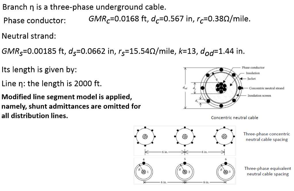
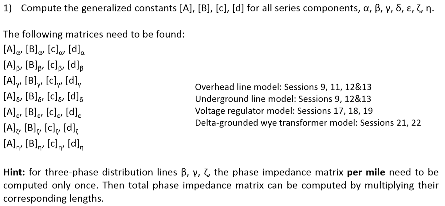
1) Compute the generalized constants [A], [B], [c], [d] for all series components, a, b, y, 6, 8, , n. (30 points) Implement the forward and backward sweeps, and compute the three-phase line-neutral voltages for all nodes, 1, 2, 3, 4, 5, 6, 7, 8. Set Tol = 0.01%, i.e. for every line-to-neutral voltage of every node, the magnitude change compared to the last iteration is less than 0.01%. (50 points) 3) Suppose node 7 is the load center. Find tap positions Tapa, Tapb, Tapc for the voltage regulator 6, which can bring all three line-to-neutral voltages of node 7 to the range of 119V and 121V on the 120V basis. (Equivalently, to the range of 2380V toe 2005 16 algorithm to verify your answer. (20 points) 4) When the regulator 8 is operated at the tap positions found in part 3), Find three-phase shunt capacitance values Ca4, Cb4, Cc4, which can bring all three line-to-neutral voltages of node 4 to the range of 119V and 121V on the 120V basis. (Equivalently, to the range of 2380V and 2420V on the 2400V basis.) Use the power flow analysis algorithm to verify your answer. (+20 points) An 8-node distribution feeder is shown in the figure below. It operates at the frequency of 60 Hz. Node 1 is the source node. Its voltage is given by [V] [ 12470230 7 abc Ji [VLLabe]. = Vbc = 12470290 V [vca] [124702-150] There are loads at node 4, 6, 7, and 8. [250+ j1207 [100+ j607 [Sabe ) = 300+ j100 (kW + jkvar) [Sabela = |(kW + jkvar) | 200+ 190] [ 0 ] [200+ j1007 [Sabe], = | 270+ j120|(kW + jkvar) | 200+ j80] [250+ j100] [Sabe] =| 300+ j120 (kW + jkvar) [290+ j100] Initially, there is no shunt capacitor at node 4. Branch a is a delta-grounded wye connected transformer. It consists of three single- phase transformers, which have the same rating and impedance: 5000 KVA, 12.47 -2.4 kV (nt = 12.47/2.455.196), Z = 0.015 +j0.08 per unit Branch is a wye-connected, type-B voltage regulator. The tap positions of the three phases can be controlled individually. (i.e. it is not gang-operated.) Initially, the tap positions are Tapa = 0, Tapb = 0, Tapc = 0 Branches B, y, and are three-phase, four-wire overhead lines. They have the same type of conductors, and the same geometry configuration. Phase conductor: GMRP abc=0.0216 ft, rp abc=0.298 N/mile. Neutral conductor: GMRn_abc=0.00773 ft, rn_abc=0.5580 1/mile. They have different lengths: k3f 5 ft Line B: the length is 1500 ft. Line 4ft - V: the length is 2000 ft. Line 7: the length is 2500 ft. b . 16 ft Branch is a single-phase (phase a only), two-wire overhead line. 6f Phase conductor: GMRp_q=0.0186 ft, rp_q=0.328 N/mile. Neutral conductor: GMRn =0.00665 ft, rn q=0.6220 N/mile. 20 ft Its length is given by: Line : the length is 1000 ft. Branch is a three-phase underground cable. Phase conductor: GMRc=0.0168 ft, dc=0.567 in, rc=0.3892/mile. Neutral strand: GMRS=0.00185 ft, ds=0.0662 in, rs=15.549/mile, k=13, dod=1.44 in. Phase conductor - Insulation Jacket - Concentric neutral strand Its length is given by: Line : the length is 2000 ft. Modified line segment model is applied, namely, shunt admittances are omitted for all distribution lines. - Insulation screen Concentric neutral cable Three-phase concentric neutral cable spacing 6 in. - * 6 in. 88 Three-phase equivalent neutral cable spacing 6 in 1) Compute the generalized constants [A], [B], [c], [d] for all series components, a, b, y, 8, , 3, n. The following matrices need to be found: [A] [B] [c] [d]. [A]y, [B]y, [c]y, [d]y [A]g, [B]g, [c], [d] [A], [B]g, [c], [d]e [A], [B], [C], [d] [A]n, [B], [C] , [d], Overhead line model: Sessions 9, 11, 12&13 Underground line model: Sessions 9, 12&13 Voltage regulator model: Sessions 17, 18, 19 Delta-grounded wye transformer model: Sessions 21, 22 Hint: for three-phase distribution lines B, Y, 5, the phase impedance matrix per mile need to be computed only once. Then total phase impedance matrix can be computed by multiplying their corresponding lengths. 1) Compute the generalized constants [A], [B], [c], [d] for all series components, a, b, y, 6, 8, , n. (30 points) Implement the forward and backward sweeps, and compute the three-phase line-neutral voltages for all nodes, 1, 2, 3, 4, 5, 6, 7, 8. Set Tol = 0.01%, i.e. for every line-to-neutral voltage of every node, the magnitude change compared to the last iteration is less than 0.01%. (50 points) 3) Suppose node 7 is the load center. Find tap positions Tapa, Tapb, Tapc for the voltage regulator 6, which can bring all three line-to-neutral voltages of node 7 to the range of 119V and 121V on the 120V basis. (Equivalently, to the range of 2380V toe 2005 16 algorithm to verify your answer. (20 points) 4) When the regulator 8 is operated at the tap positions found in part 3), Find three-phase shunt capacitance values Ca4, Cb4, Cc4, which can bring all three line-to-neutral voltages of node 4 to the range of 119V and 121V on the 120V basis. (Equivalently, to the range of 2380V and 2420V on the 2400V basis.) Use the power flow analysis algorithm to verify your answer. (+20 points) An 8-node distribution feeder is shown in the figure below. It operates at the frequency of 60 Hz. Node 1 is the source node. Its voltage is given by [V] [ 12470230 7 abc Ji [VLLabe]. = Vbc = 12470290 V [vca] [124702-150] There are loads at node 4, 6, 7, and 8. [250+ j1207 [100+ j607 [Sabe ) = 300+ j100 (kW + jkvar) [Sabela = |(kW + jkvar) | 200+ 190] [ 0 ] [200+ j1007 [Sabe], = | 270+ j120|(kW + jkvar) | 200+ j80] [250+ j100] [Sabe] =| 300+ j120 (kW + jkvar) [290+ j100] Initially, there is no shunt capacitor at node 4. Branch a is a delta-grounded wye connected transformer. It consists of three single- phase transformers, which have the same rating and impedance: 5000 KVA, 12.47 -2.4 kV (nt = 12.47/2.455.196), Z = 0.015 +j0.08 per unit Branch is a wye-connected, type-B voltage regulator. The tap positions of the three phases can be controlled individually. (i.e. it is not gang-operated.) Initially, the tap positions are Tapa = 0, Tapb = 0, Tapc = 0 Branches B, y, and are three-phase, four-wire overhead lines. They have the same type of conductors, and the same geometry configuration. Phase conductor: GMRP abc=0.0216 ft, rp abc=0.298 N/mile. Neutral conductor: GMRn_abc=0.00773 ft, rn_abc=0.5580 1/mile. They have different lengths: k3f 5 ft Line B: the length is 1500 ft. Line 4ft - V: the length is 2000 ft. Line 7: the length is 2500 ft. b . 16 ft Branch is a single-phase (phase a only), two-wire overhead line. 6f Phase conductor: GMRp_q=0.0186 ft, rp_q=0.328 N/mile. Neutral conductor: GMRn =0.00665 ft, rn q=0.6220 N/mile. 20 ft Its length is given by: Line : the length is 1000 ft. Branch is a three-phase underground cable. Phase conductor: GMRc=0.0168 ft, dc=0.567 in, rc=0.3892/mile. Neutral strand: GMRS=0.00185 ft, ds=0.0662 in, rs=15.549/mile, k=13, dod=1.44 in. Phase conductor - Insulation Jacket - Concentric neutral strand Its length is given by: Line : the length is 2000 ft. Modified line segment model is applied, namely, shunt admittances are omitted for all distribution lines. - Insulation screen Concentric neutral cable Three-phase concentric neutral cable spacing 6 in. - * 6 in. 88 Three-phase equivalent neutral cable spacing 6 in 1) Compute the generalized constants [A], [B], [c], [d] for all series components, a, b, y, 8, , 3, n. The following matrices need to be found: [A] [B] [c] [d]. [A]y, [B]y, [c]y, [d]y [A]g, [B]g, [c], [d] [A], [B]g, [c], [d]e [A], [B], [C], [d] [A]n, [B], [C] , [d], Overhead line model: Sessions 9, 11, 12&13 Underground line model: Sessions 9, 12&13 Voltage regulator model: Sessions 17, 18, 19 Delta-grounded wye transformer model: Sessions 21, 22 Hint: for three-phase distribution lines B, Y, 5, the phase impedance matrix per mile need to be computed only once. Then total phase impedance matrix can be computed by multiplying their corresponding lengths
Step by Step Solution
There are 3 Steps involved in it

Get step-by-step solutions from verified subject matter experts