

Question: Please answer the following in detail given the lab report and data shown below: 1. Resistance, R, is defined using R = V/I where V
Please answer the following in detail given the lab report and data shown below:
1. Resistance, R, is defined using R = V/I where V is the voltage across a resistor, and I is the current. R is measured in ohms (?), where 1 ? = 1 V/A. The constant determined in each equation should be similar to the resistance of each resistor. However, resistors are manufactured such that their actual value is within a tolerance. Examine the resistors' color codes to determine the tolerance of the resistors you are using. Calculate the range of values for each resistor. Does the constant in each equation fit within the appropriate range of values for each resistor?
2. Do the resistors follow Ohm's law? Base the answer on the experimental data.
3. Describe what happened to the current through the light bulb as the voltage increased. Was the relationship linear? Determine the resistance at each voltage and enter the results in the data table. Describe what happened to the resistance as the voltage increased. Since the bulb gets brighter as it gets hotter, how does the resistance vary with temperature?
3. Does the light bulb obey Ohm's law? Base your answer on your experimental data.
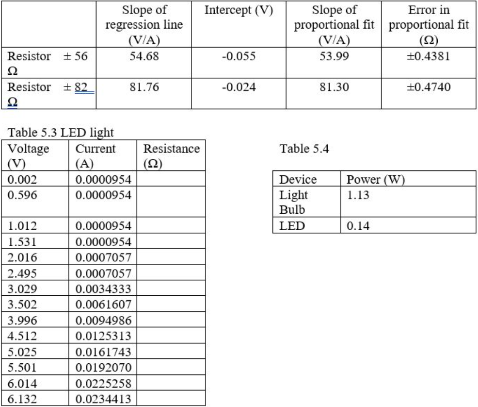
4. Describe what happened to the current through the LED as the potential difference increased. Was the relationship linear? Determine the resistance for each voltage and enter the results in the data table. Describe what happened to the resistance as the voltage increased.
5. For the maximum voltage settings in each case, calculate the corresponding electrical power, P, being consumed by the light bulb and LED. (Recall that P = IV.) P represents the rate at which electrical energy is being converted into other forms, such as light and thermal energy. Which device appears to be more efficient at producing light? If you have any questions don't hesitate to ask! Thank you so much :)
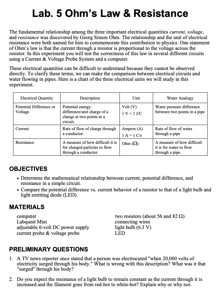
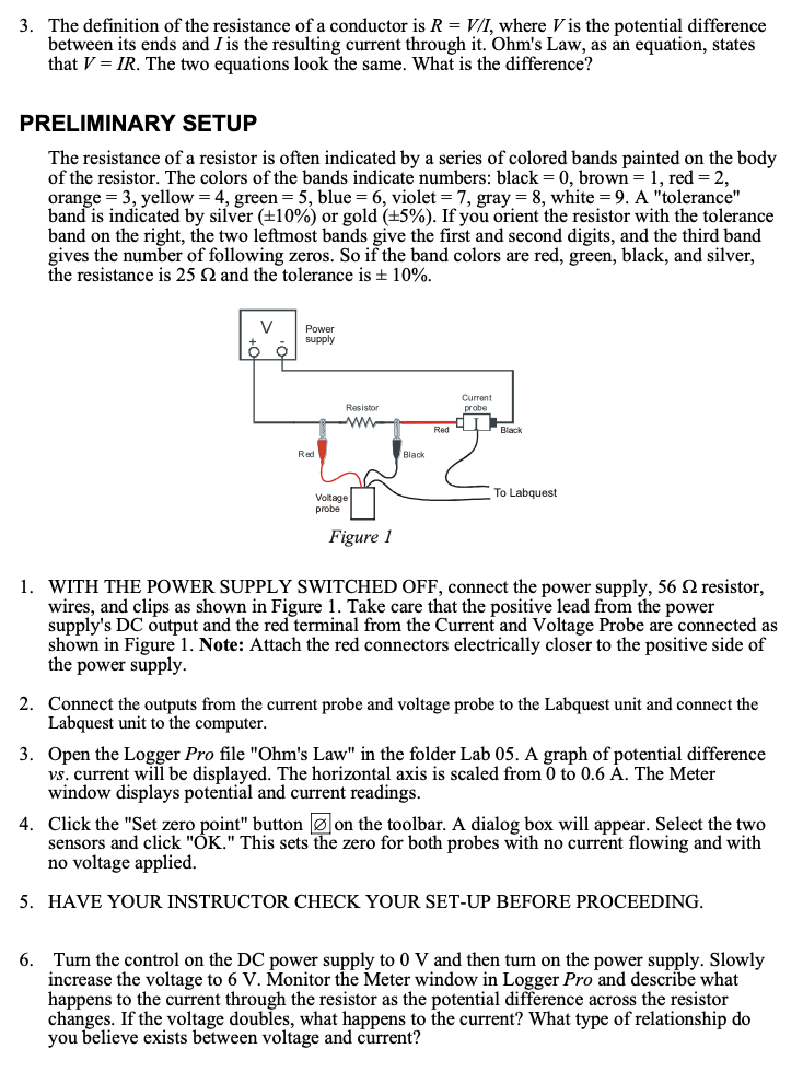
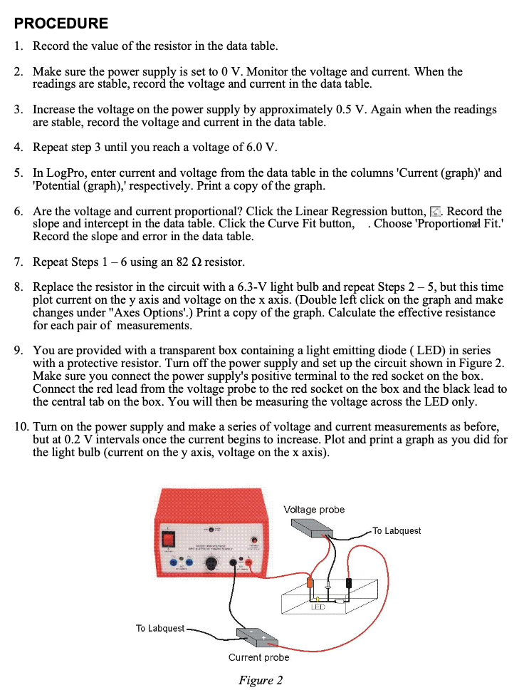
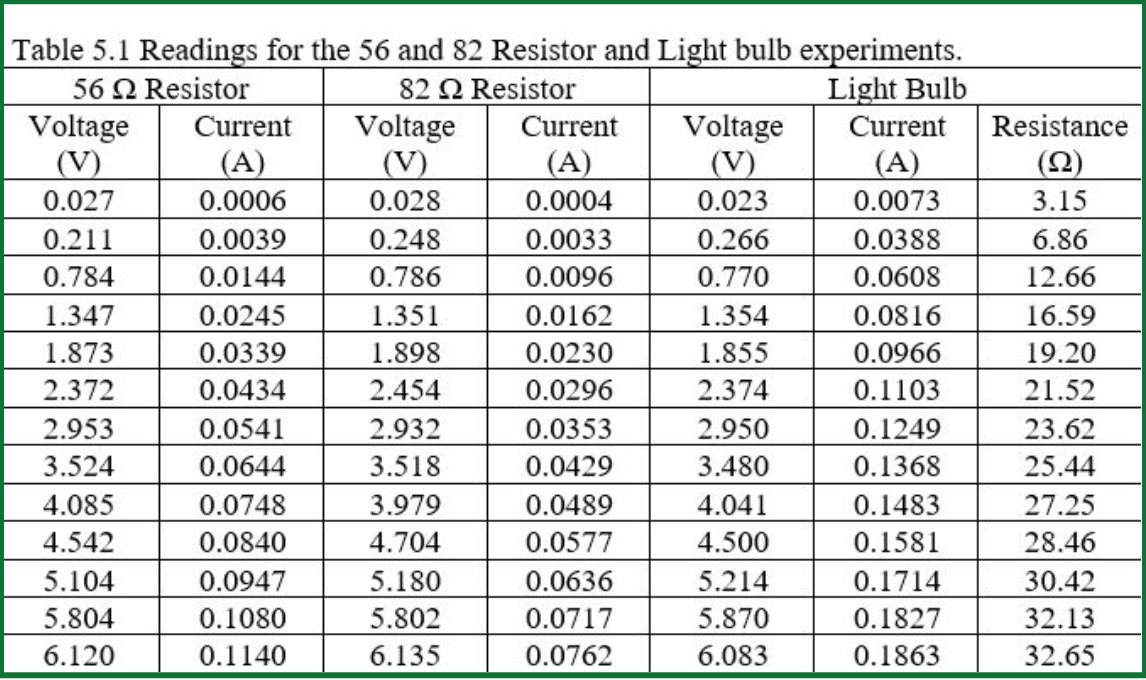
Lab. 5 Ohm's Law & Resistance The fundamental relationship among the three important electrical quantities current, voltage, and resistance was discovered by Georg Simon Ohm. The relationship and the unit of electrical resistance were both named for him to commemorate this contribution to physics. One statement of Ohm's law is that the current through a resistor is proportional to the voltage across the resistor. In this experiment you will test the correctness of this law in several different circuits using a Current & Voltage Probe System and a computer. These electrical quantities can be difficult to understand because they cannot be observed directly. To clarify these terms, we can make the comparison between electrical circuits and water flowing in pipes. Here is a chart of the three electrical units we will study in this experiment. Electrical Quantity Description Unit Water Analogy Potential Difference or Potential energy Volt (V) Water pressure difference Voltage difference/unit charge of a 1 V = 1J/C between two points in a pipe charge at two points in a circuit. Current Rate of flow of charge through Ampere (A) Rate of flow of water a conductor. 1 A = 1 C/s through a pipe Resistance A measure of how difficult it is Ohm () A measure of how difficult for charged particles to flow it is for water to flow through a conductor. through a pipe. OBJECTIVES . Determine the mathematical relationship between current, potential difference, and resistance in a simple circuit. . Compare the potential difference vs. current behavior of a resistor to that of a light bulb and light emitting diode (LED). MATERIALS computer two resistors (about 56 and 82 0) Labquest Mini connecting wires adjustable 6-volt DC power supply light bulb (6.3 V) current probe & voltage probe LED PRELIMINARY QUESTIONS 1. A TV news reporter once stated that a person was electrocuted "when 20,000 volts of electricity surged through his body." What is wrong with this description? What was it that "surged" through his body? 2. Do you expect the resistance of a light bulb to remain constant as the current through it is increased and the filament goes from red-hot to white-hot? Explain why or why not.3. The denition of the resistance of a conductor is R = VAT, where Vis the potential difference between its ends and I is the resulting current through it. Ohm's Law, as an equation, states that V = IR. The two equations look the same. What is the difference? PRELIMINARY SETUP The resistance of a resistor is often indicated by a series of colored bands painted on the body of the resistor. The colors of the bands indicate numbers: black = 0, brown = 1, red = 2, orange = 3, yellow = 4, green = 5, blue = 6, violet = 7, gray = 3, white = 9. A \"tolerance\" band is indicated by silver (i10%) or gold (35%). If you orient the resistor with the tolerance band on the right, the two leftmost bands give the first and second digits, and the third band gives the number of following zeros. So if the band colors are red, green, black, and silver, the resistance is 25 Q and the tolerance is :t: 10%. {Surre'lt rmna Blacl We\" T1: Labquast pmbe F igune l 1. WITH THE POWER SUPPLY SWITCHED OFF, connect the power supply, 56 Q resistor, wires, and clips as shown in Figure 1. Take care that the positive lead From the power supply's DC output and the red terminal from the Current and Voltage Probe are connected as shown in Figure 1. Note: Attach the red connectors electrically closer to the positive side of the power supply. 2. Connect the outputs from the current probe and voltage probe to the Labquest unit and connect the Labquest unit to the computer. 3. Open the Logger Pro file "Ohm's Law" in the folder Lab 05. A graph of potential difference vs. current will be displayed. The horizontal axis is scaled from 0 to 0.6 A. The Meter window displays potential and current readings. 4. Click the "Set zero point" button Eon the toolbar. A dialog box will appear. Select the two sensors and click "OK." This sets the zero for both probes with no current flowing and with no voltage applied. 5. HAVE YOUR INSTRUCTOR CHECK YOUR SET-UP BEFORE PROCEEDING. 6. Turn the control on the DC power supply to 0 V and then turn on the power supply. Slowly increase the voltage to 6 V. Monitor the Meter window in Logger Pro and describe what happens to the current through the resistor as the potential difference across the resistor changes. If the voltage doubles, what happens to the current? What type of relationship do you believe exists between voltage and current? PROCEDURE 1. 2. 10. Record the value of the resistor in the data table. Make sure the power supply is set to 0 V. Monitor the voltage and current. When the readings are stable, record the voltage and current in the data table. . Increase the voltage on the power supply by approximately 0.5 V. Again when the readings are stable, record the voltage and current in the data table. Repeat step 3 until you reach a voltage of 6.0 V. . In LogPro, enter current and voltage from the data table in the columns rCurrent [graph)' and rPotential (graph),r respectively. Print a copy of the graph. Are the voltage and current proportional? Click the Linear Regmssion button, E, Record the slope and intercept in the data table. Click the Curve Fit button, . Choose rProportional Fit.r Record the slope and error in the data table. Repeat Steps 1 6 using an 82 Q resistor. Replace the resistor in the circuit with a 6.3-V light bulb and repeat Steps 2 5, but this time plot current on the y axis and voltage on the x axis. (Double left click on the graph and make changes under "Axes Options'.) Print a copy of the graph. Calculate the effective resistance for each pair of measurements. You are provided with a transparent box containing a light emitting diode ( LED) in series with a protective resistor. Turn off the power supply and set up the circuit shown in Figure 2. Make sure you connect the power supply's positive terminal to the red socket on the box. Connect the red lead from the voltage probe to the red socket on the box and the black lead to the central tab on the box. You will then be measuring the voltage across the LED only. Turn on the power supply and make a series of voltage and current measurements as before, but at 0.2 V intervals once the current begins to increase. Plot and print a graph as you did for the light bulb (current on the y axis, voltage on the x axis). Voltage probe To L abq u est To Labquest Cu rrent probe Figure 2 Table 5.1 Readings for the 56 and 82 Resistor and Light bulb experiments. 56 2 Resistor 82 2 Resistor Light Bulb Voltage Current Voltage Current Voltage Current Resistance (V) (A) (V) (A) (V) (A) (2) 0.027 0.0006 0.028 0.0004 0.023 0.0073 3.15 0.211 0.0039 0.248 0.0033 0.266 0.0388 6.86 0.784 0.0144 0.786 0.0096 0.770 0.0608 12.66 1.347 0.0245 1.351 0.0162 1.354 0.0816 16.59 1.873 0.0339 1.898 0.0230 1.855 0.0966 19.20 2.372 0.0434 2.454 0.0296 2.374 0.1103 21.52 2.953 0.0541 2.932 0.0353 2.950 0.1249 23.62 3.524 0.0644 3.518 0.0429 3.480 0.1368 25.44 4.085 0.0748 3.979 0.0489 4.041 0.1483 27.25 4.542 0.0840 4.704 0.0577 4.500 0.1581 28.46 5.104 0.0947 5.180 0.0636 5.214 0.1714 30.42 5.804 0.1080 5.802 0.0717 5.870 0.1827 32.13 6.120 0.1140 6.135 0.0762 6.083 0.1863 32.65Slope of Intercept (V) Slope of Error in regression line proportional fit proportional fit (V/A) (V/A) (2) Resistor +56 54.68 -0.055 53.99 10.4381 Resistor + 82 81.76 -0.024 81.30 10.4740 Q Table 5.3 LED light Voltage Current Resistance Table 5.4 (V) (A) 0.002 0.0000954 Device Power (W) 0.596 0.0000954 Light 1.13 Bulb 1.012 0.0000954 LED 0.14 1.531 0.0000954 2.016 0.0007057 2.495 0.0007057 3.029 0.0034333 3.502 0.0061607 3.996 0.0094986 4.512 0.0125313 5.025 0.0161743 5.501 0.0192070 6.014 0.0225258 6.132 0.0234413
Step by Step Solution
There are 3 Steps involved in it

Get step-by-step solutions from verified subject matter experts