Answered step by step
Verified Expert Solution
Link Copied!

Question

1 Approved Answer

Please answer the questionuse the data from the graph. 1.3 a) Sketch the signal waveform at the transmitter for the case of the 100 ohm

Please answer the questionuse the data from the graph. image text in transcribed
image text in transcribed
1.3 a) Sketch the signal waveform at the transmitter for the case of the 100 ohm termination, and on the same plot, sketch the theoretical result for the same scenario. Account for any differences between the experimental results and the theoretical predictions ON 0 Triad M. Pos -132 Ons arsor Type Amplitude Source gh1 AV 80V Cursor 3.52v 2 Amplitude 2.00V Cursor 2 72DmV 4.16V 1 Peak Peak 3.44V 2 200V M 100ns Ext/.168mV 500.003KHZ Nov 18, 2021, 14:43 TBS 1052B-EDU - 15:05:53 18/11/2021 1.3 b) Sketch the received waveform for the case of a 1 nF termination. Qualitatively account for the shape of the reflected pulse in the time domain. ON 2 0 M.Pos -132 Ons Measure Measure Gating On Off dh1 Ch2 Math Pos Width Pos Width Amplitude 2.00V 112.8ns 100.8ns? Maximum 4.80V Snapshot 5.28V 1 Maximum 2.96V 2 2.00V M 100ns Ext/-168mV 500.003kHz Nov 18, 2021, 14:53 TBS 1052B-EDU - 15:15:16 18/11/2021 3 1.4 b): Sketch the reflected pulse received back at the pulse generator in the case of both the 10 m and 20 m cables being terminated in open circuits. In as much detail as you can, account for the delays to the first four reflections, their relative heights, and their polarities. O Co O B Trigd M Pos_336. Ons Cursor Type Time Source Gh1 A 128ns A7.812MHz AV 0.00V Cursor 1 580 Ons -40. Om 1.00V 2. Cursor 2 452. Ons - 40 Omv 1.00V M 100ns Ch2/1.44V 500.003kHz Nov 18, 2021, 16.10 TBS 1052B-EDU - 16:33:12 18/11/2021 15 1.4 c): What resistor values should be used in the matched divider and why? With these resistors fitted and all transmission lines terminated in their characteristic impedance, what percentage of the energy in the transmitted pulse is absorbed in each of the termination resistors at the ends of the output cables (the cables not directly connected to the pulse generator)

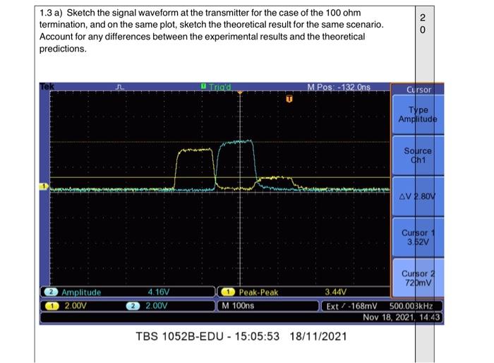
Step by Step Solution

There are 3 Steps involved in it

Step: 1

blur-text-image

Get Instant Access to Expert-Tailored Solutions

See step-by-step solutions with expert insights and AI powered tools for academic success

Step: 2

blur-text-image

Step: 3

blur-text-image

Ace Your Homework with AI

Get the answers you need in no time with our AI-driven, step-by-step assistance

Get Started

Students also viewed these Databases questions

Question

x-3+1, x23 Let f(x) = -*+3, * Answered: 1 week ago

Answered: 1 week ago