Answered step by step
Verified Expert Solution
Link Copied!

Question

1 Approved Answer

Please do it with ltspice Preliminary work: 1. Analyze the following circuit. Calculate the capacitor voltage as a function of time for 5V step input.

Please do it with ltspiceimage text in transcribed

Preliminary work: 1. Analyze the following circuit. Calculate the capacitor voltage as a function of time for 5V step input. (R=1k, C=200nF). Assume initial capacitor voltage is zero. R o + vs(tRS vct) 2. Verify your calculations using SPICE. 3. Read the data sheet of LM555 timer circuit. Using the timer IC, build a circuit that will blink an LED continuously with 1 sec time period. The LED should be on for 0.5 sec and off for 0.5 sec. For this part do the followings: 1. Search internet, choose an application circuit that will generate square wave oscillation using LM555. Adjust the frequency by properly selecting R and C values. Show your calculations on how you determined the frequency of oscillations Read the data sheet of typical LEDs. Connect an LED to the output of the timer with proper bias resistor. Calculate the value of the bias resistor as suggested in the data sheet. 2. a Task 2. Timer circuit: 1. Set-up the timer circuit that you designed in the second part of the preliminary work. Demonstrate that the LED flashes with 1 sec periods. Measure the frequency of the timer output using the scope. Try to do fine adjustment to get exactly 1 sec period (or 1Hz frequency). Preliminary work: 1. Analyze the following circuit. Calculate the capacitor voltage as a function of time for 5V step input. (R=1k, C=200nF). Assume initial capacitor voltage is zero. R o + vs(tRS vct) 2. Verify your calculations using SPICE. 3. Read the data sheet of LM555 timer circuit. Using the timer IC, build a circuit that will blink an LED continuously with 1 sec time period. The LED should be on for 0.5 sec and off for 0.5 sec. For this part do the followings: 1. Search internet, choose an application circuit that will generate square wave oscillation using LM555. Adjust the frequency by properly selecting R and C values. Show your calculations on how you determined the frequency of oscillations Read the data sheet of typical LEDs. Connect an LED to the output of the timer with proper bias resistor. Calculate the value of the bias resistor as suggested in the data sheet. 2. a Task 2. Timer circuit: 1. Set-up the timer circuit that you designed in the second part of the preliminary work. Demonstrate that the LED flashes with 1 sec periods. Measure the frequency of the timer output using the scope. Try to do fine adjustment to get exactly 1 sec period (or 1Hz frequency)

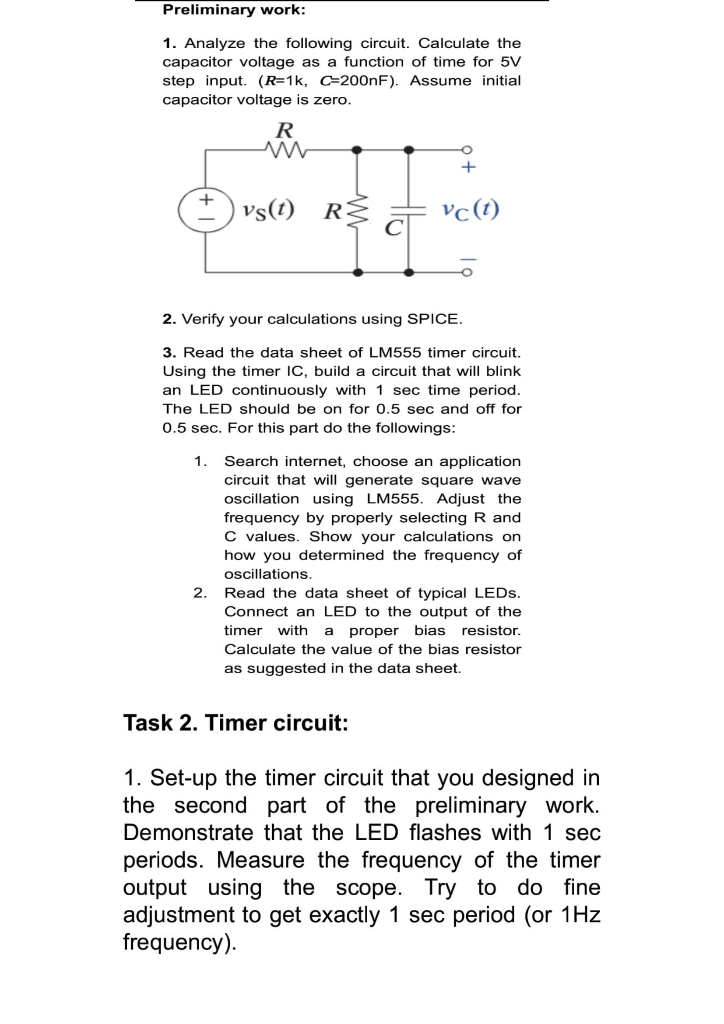
Step by Step Solution

There are 3 Steps involved in it

Step: 1

blur-text-image

Get Instant Access to Expert-Tailored Solutions

See step-by-step solutions with expert insights and AI powered tools for academic success

Step: 2

blur-text-image

Step: 3

blur-text-image

Ace Your Homework with AI

Get the answers you need in no time with our AI-driven, step-by-step assistance

Get Started

Recommended Textbook for

Financial Accounting Standards Board Webster S Timeline History 1971 2006

Authors: Icon Group International

1st Edition

0546876501, 978-0546876505

More Books

Students also viewed these Accounting questions