Please draw a flow chart for the following Program

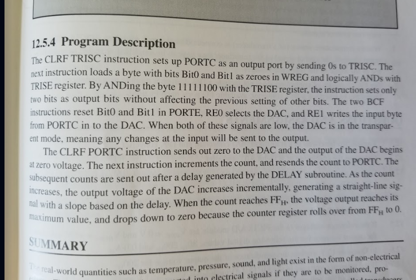
12.5.4 Program Description The CLRF TRISC instruction sets up PORTC as an output port by sending Os to TRISC. The next instruction loads a byte with bits Bito and Bitl as zeroes in WREG and logically ANDs with TRISE register. By ANDing the byte 11111100 with the TRISE register, the instruction sets only two bits as output bits without affecting the previous setting of other bits. The two BCF instructions reset Bit0 and Bitl in PORTE, REO selects the DAC, and RE1 writes the input byte from PORTC in to the DAC. When both of these signals are low, the DAC is in the transpar- ent mode, meaning any changes at the input will be sent to the output. The CLRF PORTC instruction sends out zero to the DAC and the output of the DAC begins at zero voltage. The next instruction increments the count, and resends the count to PORTC. The subsequent counts are sent out after a delay generated by the DELAY subroutine. As the count increases, the output voltage of the DAC increases incrementally, generating a straight-line sig- udl with a slope based on the delay. When the count reaches FFH, the voltage output reaches its mum value, and drops down to zero because the counter register rolls over from FF to 0. SUMMARY al-world quantities such as temperature, pressure, sound, and light exist in the form of non-electrical tad into electrical signals if they are to be monitored, pro- 12.5.4 Program Description The CLRF TRISC instruction sets up PORTC as an output port by sending Os to TRISC. The next instruction loads a byte with bits Bito and Bitl as zeroes in WREG and logically ANDs with TRISE register. By ANDing the byte 11111100 with the TRISE register, the instruction sets only two bits as output bits without affecting the previous setting of other bits. The two BCF instructions reset Bit0 and Bitl in PORTE, REO selects the DAC, and RE1 writes the input byte from PORTC in to the DAC. When both of these signals are low, the DAC is in the transpar- ent mode, meaning any changes at the input will be sent to the output. The CLRF PORTC instruction sends out zero to the DAC and the output of the DAC begins at zero voltage. The next instruction increments the count, and resends the count to PORTC. The subsequent counts are sent out after a delay generated by the DELAY subroutine. As the count increases, the output voltage of the DAC increases incrementally, generating a straight-line sig- udl with a slope based on the delay. When the count reaches FFH, the voltage output reaches its mum value, and drops down to zero because the counter register rolls over from FF to 0. SUMMARY al-world quantities such as temperature, pressure, sound, and light exist in the form of non-electrical tad into electrical signals if they are to be monitored, pro


