Answered step by step
Verified Expert Solution
Question
1 Approved Answer
Please draw the ladder logic and show full detail for full credit Problem 2: In following Tank, when the start button is activated, the control
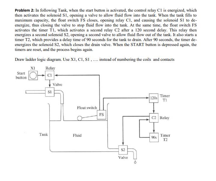
Please draw the ladder logic and show full detail for full credit
Problem 2: In following Tank, when the start button is activated, the control relay Cl is energized, which then activates the solenoid S maximum capacity, the float switch FS closes, opening relay C, and causing the solenoid SI to de- energize, thus closing the valve to stop fluid flow into the tank. At the same time, the float switch FS activates the timer T1, which activates a second relay C2 after a 120 second delay. This relay then energizes a second solenoid S2, opening a second valve to allow fluid flow out of the tank. It also starts a timer T2, which provides a delay time of 90 seconds for the tank to drain. After 90 seconds, the timer de energizes the solenoid S2, which closes the drain valve. When the START button is depressed again, the timers are reset, and the process begins again. 1, opening a valve to allow fluid flow into the tank. When the tank fills to r logic diagram. Use X1, C1, S.. tead of numbering the coils and contacts o X1 Relay Start button Valve S1 120s Timer Ti Float switch FS C2 Relay Tank Fluid 90s imer T2 S2 Valve Problem 2: In following Tank, when the start button is activated, the control relay Cl is energized, which then activates the solenoid S maximum capacity, the float switch FS closes, opening relay C, and causing the solenoid SI to de- energize, thus closing the valve to stop fluid flow into the tank. At the same time, the float switch FS activates the timer T1, which activates a second relay C2 after a 120 second delay. This relay then energizes a second solenoid S2, opening a second valve to allow fluid flow out of the tank. It also starts a timer T2, which provides a delay time of 90 seconds for the tank to drain. After 90 seconds, the timer de energizes the solenoid S2, which closes the drain valve. When the START button is depressed again, the timers are reset, and the process begins again. 1, opening a valve to allow fluid flow into the tank. When the tank fills to r logic diagram. Use X1, C1, S.. tead of numbering the coils and contacts o X1 Relay Start button Valve S1 120s Timer Ti Float switch FS C2 Relay Tank Fluid 90s imer T2 S2 ValveStep by Step Solution
There are 3 Steps involved in it
Step: 1
Get Instant Access to Expert-Tailored Solutions
See step-by-step solutions with expert insights and AI powered tools for academic success
Step: 2
Step: 3
Ace Your Homework with AI
Get the answers you need in no time with our AI-driven, step-by-step assistance
Get Started