Answered step by step
Verified Expert Solution
Link Copied!

Question

1 Approved Answer

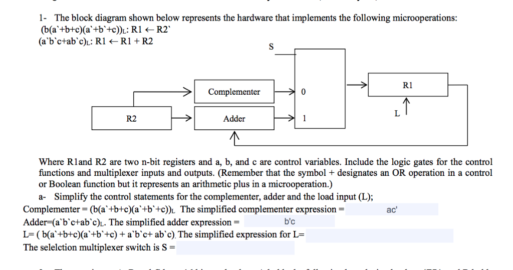
Please help! 1- The block diagram shown below represents the hardware that implements the following microoperations: R1 Complementer 0 R2 Adder Where Rland R2 are

Please help!

image text in transcribed

1- The block diagram shown below represents the hardware that implements the following microoperations: R1 Complementer 0 R2 Adder Where Rland R2 are two n-bit registers and a, b, and c are control variables. Include the logic gates for the control functions and multiplexer inputs and outputs. (Remember that the symbol + designates an OR operation in a control or Boolean function but it represents an arithmetic plus in a microoperation.) a- Simplify the control statements for the complementer, adder and the load input (L); Complementer - (b(a+btc(a'+b+c)l The simplified complementer expression- Adder-(a'b'ctab'c)L. The simplified adder expression - L-(b(a +b+c)(a'+b'+c) + a b'ct ab'c). The simplified expression for L- The selelction multiplexer switch is S- ac' b'c

Step by Step Solution

There are 3 Steps involved in it

Step: 1

blur-text-image

Get Instant Access to Expert-Tailored Solutions

See step-by-step solutions with expert insights and AI powered tools for academic success

Step: 2

blur-text-image

Step: 3

blur-text-image

Ace Your Homework with AI

Get the answers you need in no time with our AI-driven, step-by-step assistance

Get Started

Recommended Textbook for

Database And Expert Systems Applications 31st International Conference Dexa 2020 Bratislava Slovakia September 14 17 2020 Proceedings Part 1 Lncs 12391

Authors: Sven Hartmann ,Josef Kung ,Gabriele Kotsis ,A Min Tjoa ,Ismail Khalil

1st Edition

303059002X, 978-3030590024

More Books

Students also viewed these Databases questions