

Question: please Help!! Instructions The purpose of this lab assignment is to become familiar with the Cisco Internetwork Operating System (IOS) command-line interface (CLI). Also, you
please Help!!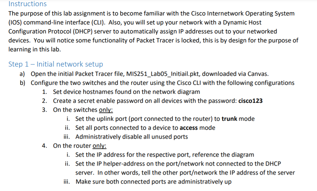
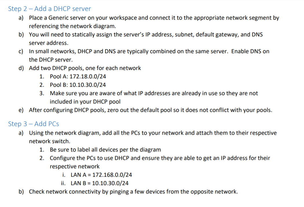
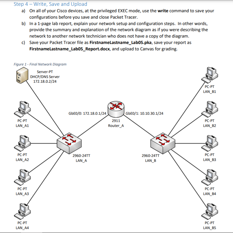
Instructions The purpose of this lab assignment is to become familiar with the Cisco Internetwork Operating System (IOS) command-line interface (CLI). Also, you will set up your network with a Dynamic Host Configuration Protocol (DHCP) server to automatically assign IP addresses out to your networked devices. You will notice some functionality of Packet Tracer is locked, this is by design for the purpose of learning in this lab. Step 1 - Initial network setup a) Open the initial Packet Tracer file, MIS251_Labo5_Initiail.pkt, downloaded via Canvas. b) Configure the two switches and the router using the Cisco CLI with the following configurations 1. Set device hostnames found on the network diagram 2. Create a secret enable password on all devices with the password: cisco123 3. On the switches only: i. Set the uplink port (port connected to the router) to trunk mode ii. Set all ports connected to a device to access mode iii. Administratively disable all unused ports 4. On the router only: i. Set the IP address for the respective port, reference the diagram ii. Set the IP helper-address on the portetwork not connected to the DHCP server. In other words, tell the other portetwork the IP address of the server iii. Make sure both connected ports are administratively up Step 2 - Add a DHCP server a) Place a Generic server on your workspace and connect it to the appropriate network segment by referencing the network diagram. b) You will need to statically assign the server's IP address, subnet, default gateway, and DNS server address. c) In small networks, DHCP and DNS are typically combined on the same server. Enable DNS on the DHCP server. d) Add two DHCP pools, one for each network 1. Pool A: 172.18.0.0/24 2. Pool B: 10.10.30.0/24 3. Make sure you are aware of what IP addresses are already in use so they are not included in your DHCP pool e) After configuring DHCP pools, zero out the default pool so it does not conflict with your pools. Step 3 - Add PCs a) Using the network diagram, add all the PCs to your network and attach them to their respective network switch. 1. Be sure to label all devices per the diagram 2. Configure the PCs to use DHCP and ensure they are able to get an IP address for their respective network i. LAN A = 172.168.0.0/24 ii. LAN B = 10.10.30.0/24 b) Check network connectivity by pinging a few devices from the opposite network. Step 4 - Write, Save and Upload a) On all of your Cisco devices, at the privileged EXEC mode, use the write command to save your configurations before you save and close Packet Tracer. b) In a 1-page lab report, explain your network setup and configuration steps. In other words, provide the summary and explanation of the network diagram as if you were describing the network to another network technician who does not have a copy of the diagram. c) Save your Packet Tracer file as FirstnameLastname_Lab05.pka, save your report as FirstnameLastname_Lab05_Report.docx, and upload to Canvas for grading. Figure 1 - Final Network Diagram Server-PT DHCP/DNS Server 172.18.0.2/24 PC-PT LAN_B1 PC-PT LAN_A1 GbE0/0: 172.18.0.1/24 GbE0/1: 10.10.30.1/24 2911 Router_A PC-PT LAN_B2 PC-PT LAN_A2 2960-24TT LAN_A 2960-24TT LAN_B PC-PT LAN_B3 PC-PT LAN_A3 PC-PT LAN_B4 PC-PT LAN_A4 PC-PT LAN_B5 Instructions The purpose of this lab assignment is to become familiar with the Cisco Internetwork Operating System (IOS) command-line interface (CLI). Also, you will set up your network with a Dynamic Host Configuration Protocol (DHCP) server to automatically assign IP addresses out to your networked devices. You will notice some functionality of Packet Tracer is locked, this is by design for the purpose of learning in this lab. Step 1 - Initial network setup a) Open the initial Packet Tracer file, MIS251_Labo5_Initiail.pkt, downloaded via Canvas. b) Configure the two switches and the router using the Cisco CLI with the following configurations 1. Set device hostnames found on the network diagram 2. Create a secret enable password on all devices with the password: cisco123 3. On the switches only: i. Set the uplink port (port connected to the router) to trunk mode ii. Set all ports connected to a device to access mode iii. Administratively disable all unused ports 4. On the router only: i. Set the IP address for the respective port, reference the diagram ii. Set the IP helper-address on the portetwork not connected to the DHCP server. In other words, tell the other portetwork the IP address of the server iii. Make sure both connected ports are administratively up Step 2 - Add a DHCP server a) Place a Generic server on your workspace and connect it to the appropriate network segment by referencing the network diagram. b) You will need to statically assign the server's IP address, subnet, default gateway, and DNS server address. c) In small networks, DHCP and DNS are typically combined on the same server. Enable DNS on the DHCP server. d) Add two DHCP pools, one for each network 1. Pool A: 172.18.0.0/24 2. Pool B: 10.10.30.0/24 3. Make sure you are aware of what IP addresses are already in use so they are not included in your DHCP pool e) After configuring DHCP pools, zero out the default pool so it does not conflict with your pools. Step 3 - Add PCs a) Using the network diagram, add all the PCs to your network and attach them to their respective network switch. 1. Be sure to label all devices per the diagram 2. Configure the PCs to use DHCP and ensure they are able to get an IP address for their respective network i. LAN A = 172.168.0.0/24 ii. LAN B = 10.10.30.0/24 b) Check network connectivity by pinging a few devices from the opposite network. Step 4 - Write, Save and Upload a) On all of your Cisco devices, at the privileged EXEC mode, use the write command to save your configurations before you save and close Packet Tracer. b) In a 1-page lab report, explain your network setup and configuration steps. In other words, provide the summary and explanation of the network diagram as if you were describing the network to another network technician who does not have a copy of the diagram. c) Save your Packet Tracer file as FirstnameLastname_Lab05.pka, save your report as FirstnameLastname_Lab05_Report.docx, and upload to Canvas for grading. Figure 1 - Final Network Diagram Server-PT DHCP/DNS Server 172.18.0.2/24 PC-PT LAN_B1 PC-PT LAN_A1 GbE0/0: 172.18.0.1/24 GbE0/1: 10.10.30.1/24 2911 Router_A PC-PT LAN_B2 PC-PT LAN_A2 2960-24TT LAN_A 2960-24TT LAN_B PC-PT LAN_B3 PC-PT LAN_A3 PC-PT LAN_B4 PC-PT LAN_A4 PC-PT LAN_B5
Step by Step Solution
There are 3 Steps involved in it

Get step-by-step solutions from verified subject matter experts