

Answered step by step
Verified Expert Solution
Question
1 Approved Answer
Please help me how to do this portion. Simulator (PathSim Goal: With the completion of this lab you will understand the values placed on lines
Please help me how to do this portion.
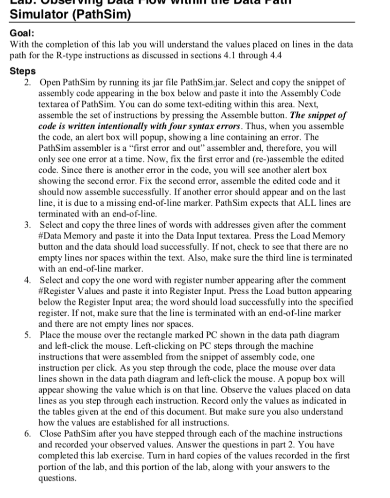
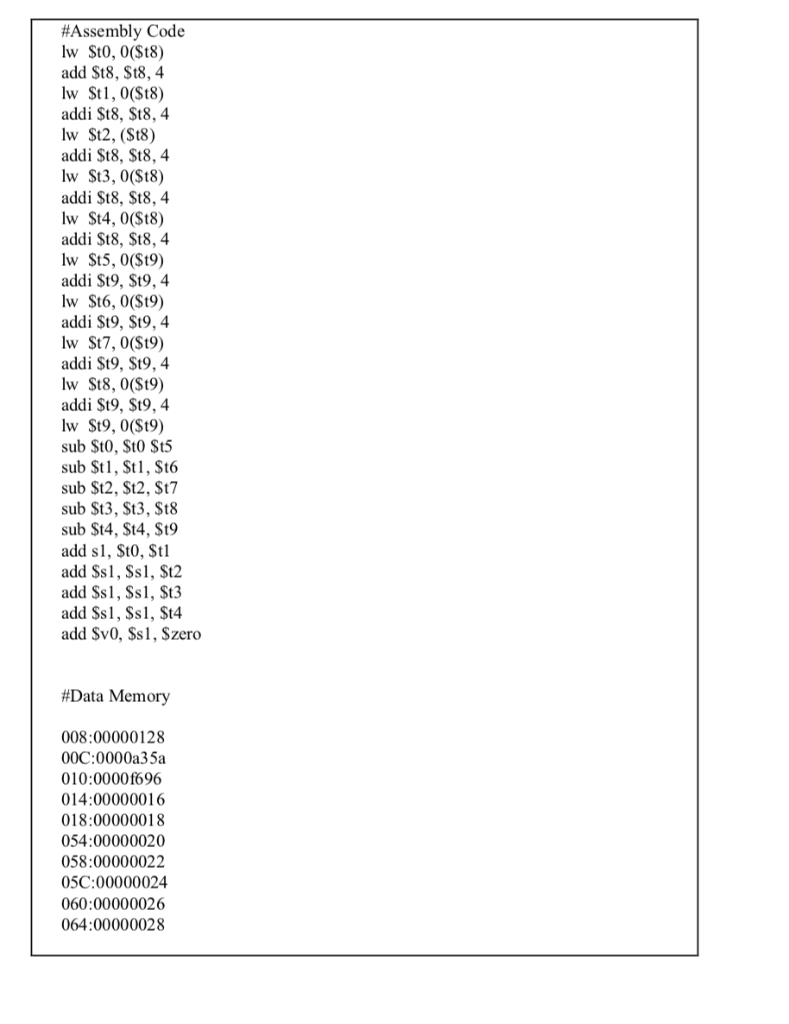
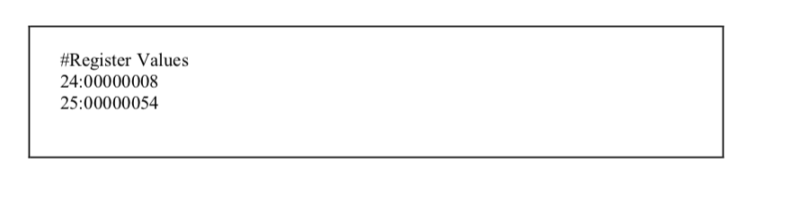
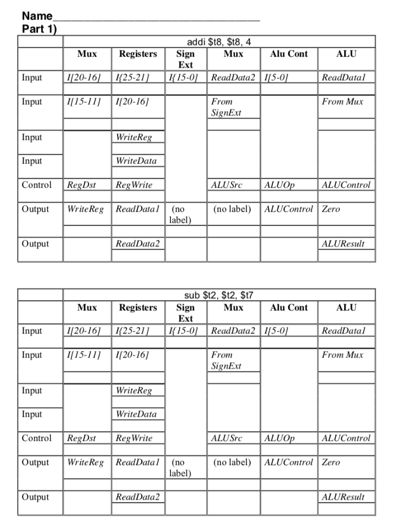
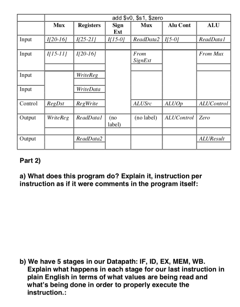
Simulator (PathSim Goal: With the completion of this lab you will understand the values placed on lines in the data path for the R-type instructions as discussed in sections 4.1 through 4.4 Steps 2. Open PathSim by running its jar file PathSim.jar. Select and copy the snippet of assembly code appearing in the box below and paste it into the Assembly Code textarea of PathSim. You can do some text-editing within this area. Next, assemble the set of instructions by pressing the Assemble button. The snippet of code is written intentionally with four syntax errors. Thus, when you assemble the code, an alert box will popup, showing a line containing an error. The PathSim assembler is a "first error and out" assembler and, therefore, you will only see one error at a time. Now, fix the first error and (re-)assemble the edited code. Since there is another error in the code, you will see another alert box showing the second error. Fix the second error, assemble the edited code and it should now assemble successfully. If another error should appear and on the last line, it is due to a missing end-of-line marker. PathSim expects that ALL lines are terminated with an end-of-line. Select and copy the three lines of words with addresses given after the comment # Data Memory and paste it into the Data Input textarea. Press the Load Memory button and the data should load successfully. If not, check to see that there are no empty lines nor spaces within the text. Also, make sure the third line is terminated with an end-of-line marker Select and copy the one word with register number appearing after the comment #Register Values and paste it into Register input. Press the Load button appearing below the Register Input area; the word should load successfully into the specified register. If not, make sure that the line is terminated with an end-of-line marker and there are not empty lines nor spaces Place the mouse over the rectangle marked PC shown in the data path diagram and left-click the mouse. Left-clicking on PC steps through the machine instructions that were assembled from the snippet of assembly code, one instruction per click. As you step through the code, place the mouse over data lines shown in the data path diagram and left-click the mouse. A popup box will appear showing the value which is on that line. Observe the values placed on data lines as you step through each instruction. Record only the values as indicated in the tables given at the end of this document. But make sure you also understand how the values are established for all instructions Close PathSim after you have stepped through each of the machine instructions and recorded your observed values. Answer the questions in part 2. You have completed this lab exercise. Turn in hard copies of the values recorded in the first portion of the lab, and this portion of the lab, along with your answers to the questions 3. 4. 5. 6. #Assembly Code add St8, St8, 4 addi St8, St8, 4 addi St8, St8, 4 addi St8, St8, 4 lw St4, 0(St8) addi St8, St8, 4 addi St9, St9,4 addi St9, St9,4 addi St9, St9,4 addi St9, St9,4 lw St9, 0(St9) sub St0, St0 St5 sub $t1, St1, St6 sub St2, St2, St7 sub St3, St3, St8 sub St4, St4, St9 add s, St0, Stl add Ssl, Ss1, St2 add Ss1, Ss1, St3 add Ss, Ss1, St4 add SvO, SsI, Szero #Data Memory 008:00000128 00C:0000a35a 010:0000f696 014:00000016 018:00000018 054:00000020 058:00000022 05C:00000024 060:00000026 064:00000028 &Register Values 24:00000008 25:00000054 Name Part 1 addi St8, St8, 4 lux Registers Sign Ext Mux Alu Cont ALU Input I[20-16] 25-21 15-0 ReadData25-0 ReadDatal Input1[15-11/1[20-16] From SignExt From Mux Input Input Control RegDst RegWrite OutpWriteReg ReadData(no WriteRe WriteData ALUSrc ALUO ALUControl (no label)ALUControl Zero label Output ReadData2 ALUResult sub $t2, $t2, $t7 Mux Registers Sign Mux Alu Cont ALU Ext Input I[20-16 I25-21 K15-01ReadData2II5-0 ReadData Input1[15-11/1120-16] From SignExt From Mux Input Input Control RegDst Reg Write OutpuWriteReg ReadData(no WriteRe WriteData ALUSrc ALUO ALUControl (no label)ALUControl Zero label Output ReadData2 ALUResult add $v0, $s1, $zero ALU ReadData l From Mux Mux RegistersSign Alu Cont Ext 5-0 ReadData2 |5-0 Input I/20-16/ 25-21 Input1115-11] 1[2016] From SignExt WriteRe Input Input Control RegDst RegWrite Output WriteRegReadData(no WriteData ALUSrc AL ALUControl no label) ALUControl Zero label Output ReadData2 ALUResult Part 2) a) What does this program do? Explain it, instruction per instruction as if it were comments in the program itself: b) We have 5 stages in our Datapath: IF, ID, EX, MEM, WB. Explain what happens in each stage for our last instruction in plain English in terms of what values are being read and what's being done in order to properly execute the instruction.: Simulator (PathSim Goal: With the completion of this lab you will understand the values placed on lines in the data path for the R-type instructions as discussed in sections 4.1 through 4.4 Steps 2. Open PathSim by running its jar file PathSim.jar. Select and copy the snippet of assembly code appearing in the box below and paste it into the Assembly Code textarea of PathSim. You can do some text-editing within this area. Next, assemble the set of instructions by pressing the Assemble button. The snippet of code is written intentionally with four syntax errors. Thus, when you assemble the code, an alert box will popup, showing a line containing an error. The PathSim assembler is a "first error and out" assembler and, therefore, you will only see one error at a time. Now, fix the first error and (re-)assemble the edited code. Since there is another error in the code, you will see another alert box showing the second error. Fix the second error, assemble the edited code and it should now assemble successfully. If another error should appear and on the last line, it is due to a missing end-of-line marker. PathSim expects that ALL lines are terminated with an end-of-line. Select and copy the three lines of words with addresses given after the comment # Data Memory and paste it into the Data Input textarea. Press the Load Memory button and the data should load successfully. If not, check to see that there are no empty lines nor spaces within the text. Also, make sure the third line is terminated with an end-of-line marker Select and copy the one word with register number appearing after the comment #Register Values and paste it into Register input. Press the Load button appearing below the Register Input area; the word should load successfully into the specified register. If not, make sure that the line is terminated with an end-of-line marker and there are not empty lines nor spaces Place the mouse over the rectangle marked PC shown in the data path diagram and left-click the mouse. Left-clicking on PC steps through the machine instructions that were assembled from the snippet of assembly code, one instruction per click. As you step through the code, place the mouse over data lines shown in the data path diagram and left-click the mouse. A popup box will appear showing the value which is on that line. Observe the values placed on data lines as you step through each instruction. Record only the values as indicated in the tables given at the end of this document. But make sure you also understand how the values are established for all instructions Close PathSim after you have stepped through each of the machine instructions and recorded your observed values. Answer the questions in part 2. You have completed this lab exercise. Turn in hard copies of the values recorded in the first portion of the lab, and this portion of the lab, along with your answers to the questions 3. 4. 5. 6. #Assembly Code add St8, St8, 4 addi St8, St8, 4 addi St8, St8, 4 addi St8, St8, 4 lw St4, 0(St8) addi St8, St8, 4 addi St9, St9,4 addi St9, St9,4 addi St9, St9,4 addi St9, St9,4 lw St9, 0(St9) sub St0, St0 St5 sub $t1, St1, St6 sub St2, St2, St7 sub St3, St3, St8 sub St4, St4, St9 add s, St0, Stl add Ssl, Ss1, St2 add Ss1, Ss1, St3 add Ss, Ss1, St4 add SvO, SsI, Szero #Data Memory 008:00000128 00C:0000a35a 010:0000f696 014:00000016 018:00000018 054:00000020 058:00000022 05C:00000024 060:00000026 064:00000028 &Register Values 24:00000008 25:00000054 Name Part 1 addi St8, St8, 4 lux Registers Sign Ext Mux Alu Cont ALU Input I[20-16] 25-21 15-0 ReadData25-0 ReadDatal Input1[15-11/1[20-16] From SignExt From Mux Input Input Control RegDst RegWrite OutpWriteReg ReadData(no WriteRe WriteData ALUSrc ALUO ALUControl (no label)ALUControl Zero label Output ReadData2 ALUResult sub $t2, $t2, $t7 Mux Registers Sign Mux Alu Cont ALU Ext Input I[20-16 I25-21 K15-01ReadData2II5-0 ReadData Input1[15-11/1120-16] From SignExt From Mux Input Input Control RegDst Reg Write OutpuWriteReg ReadData(no WriteRe WriteData ALUSrc ALUO ALUControl (no label)ALUControl Zero label Output ReadData2 ALUResult add $v0, $s1, $zero ALU ReadData l From Mux Mux RegistersSign Alu Cont Ext 5-0 ReadData2 |5-0 Input I/20-16/ 25-21 Input1115-11] 1[2016] From SignExt WriteRe Input Input Control RegDst RegWrite Output WriteRegReadData(no WriteData ALUSrc AL ALUControl no label) ALUControl Zero label Output ReadData2 ALUResult Part 2) a) What does this program do? Explain it, instruction per instruction as if it were comments in the program itself: b) We have 5 stages in our Datapath: IF, ID, EX, MEM, WB. Explain what happens in each stage for our last instruction in plain English in terms of what values are being read and what's being done in order to properly execute the instruction
Step by Step Solution
There are 3 Steps involved in it
Step: 1

Get Instant Access to Expert-Tailored Solutions
See step-by-step solutions with expert insights and AI powered tools for academic success
Step: 2

Step: 3
Ace Your Homework with AI
Get the answers you need in no time with our AI-driven, step-by-step assistance
Get Started
Data Mining Concepts And Techniques
Authors: Jiawei Han, Micheline Kamber, Jian Pei
3rd Edition
0123814790, 9780123814791