

Answered step by step
Verified Expert Solution
Question
1 Approved Answer
Please help me with question 3. 1 MSB 2 3 DB-TYPE 1 DB-TYPE 2 A new mixed-use complex is being built and you have to
Please help me with question 3.
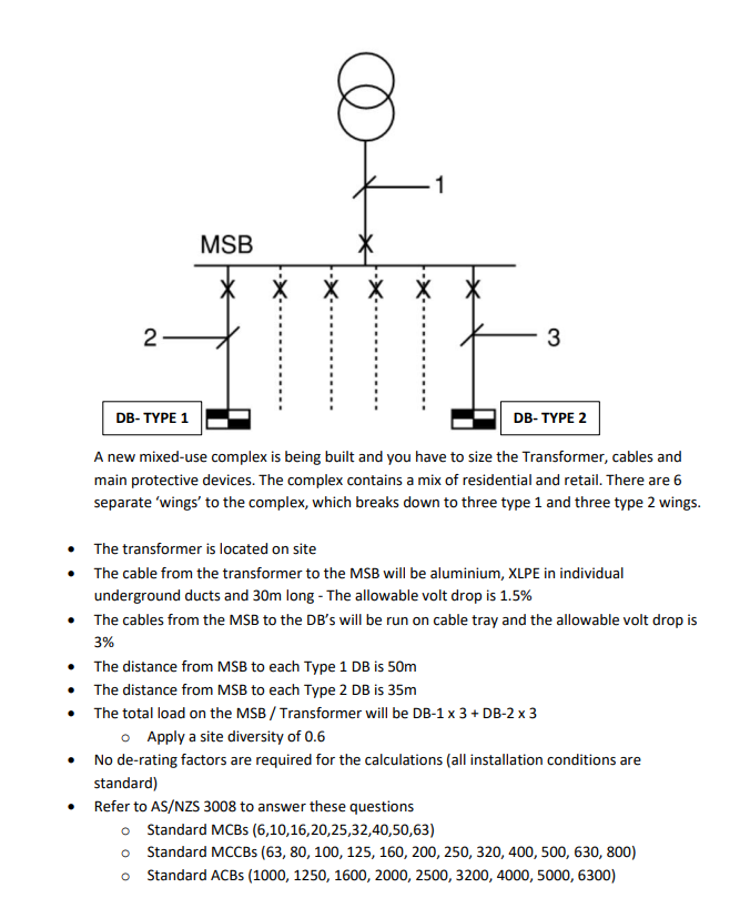
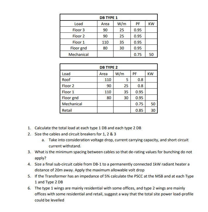
1 MSB 2 3 DB-TYPE 1 DB-TYPE 2 A new mixed-use complex is being built and you have to size the Transformer, cables and main protective devices. The complex contains a mix of residential and retail. There are 6 separate 'wings' to the complex, which breaks down to three type 1 and three type 2 wings. The transformer is located on site The cable from the transformer to the MSB will be aluminium, XLPE in individual underground ducts and 30m long - The allowable volt drop is 1.5% The cables from the MSB to the DB's will be run on cable tray and the allowable volt drop is 3% The distance from MSB to each Type 1 DB is 50m The distance from MSB to each Type 2 DB is 35m The total load on the MSB / Transformer will be DB-1 x 3 + DB-2 x 3 o Apply a site diversity of 0.6 No de-rating factors are required for the calculations (all installation conditions are standard) Refer to AS/NZS 3008 to answer these questions o Standard MCBs (6,10,16,20,25,32,40,50,63) o Standard MCCBS (63, 80, 100, 125, 160, 200, 250, 320, 400, 500, 630, 800) Standard ACBs (1000, 1250, 1600, 2000, 2500, 3200, 4000, 5000, 6300) PF KW Load Floor 3 Floor 2 Floor 1 Floor gnd Mechanical DB TYPE 1 Area W/m 90 25 90 25 110 35 80 0.95 0.95 0.95 0.95 30 0.75 50 DB TYPE 2 W/m PF KW Area 110 90 5 0.8 Load Roof Floor 2 Floor 1 Floor gnd Mechanical Retail 25 35 110 80 30 0.8 0.95 0.95 0.75 0.85 50 30 1. Calculate the total load at each type 1 DB and each type 2 DB 2. Size the cables and circuit breakers for 1, 2 & 3 a. Take into consideration voltage drop, current carrying capacity, and short circuit current withstand. 3. What is the minimum spacing between cables so that de-rating values for bunching do not apply? 4. Size a final sub-circuit cable from DB-1 to a permanently connected 1kW radiant heater a distance of 20m away. Apply the maximum allowable volt drop 5. If the Transformer has an impedance of 5% calculate the PSCC at the MSB and at each Type 1 and Type 2 DB 6. The type 1 wings are mainly residential with some offices, and type 2 wings are mainly offices with some residential and retail, suggest a way that the total site power load-profile could be levelled 1 MSB 2 3 DB-TYPE 1 DB-TYPE 2 A new mixed-use complex is being built and you have to size the Transformer, cables and main protective devices. The complex contains a mix of residential and retail. There are 6 separate 'wings' to the complex, which breaks down to three type 1 and three type 2 wings. The transformer is located on site The cable from the transformer to the MSB will be aluminium, XLPE in individual underground ducts and 30m long - The allowable volt drop is 1.5% The cables from the MSB to the DB's will be run on cable tray and the allowable volt drop is 3% The distance from MSB to each Type 1 DB is 50m The distance from MSB to each Type 2 DB is 35m The total load on the MSB / Transformer will be DB-1 x 3 + DB-2 x 3 o Apply a site diversity of 0.6 No de-rating factors are required for the calculations (all installation conditions are standard) Refer to AS/NZS 3008 to answer these questions o Standard MCBs (6,10,16,20,25,32,40,50,63) o Standard MCCBS (63, 80, 100, 125, 160, 200, 250, 320, 400, 500, 630, 800) Standard ACBs (1000, 1250, 1600, 2000, 2500, 3200, 4000, 5000, 6300) PF KW Load Floor 3 Floor 2 Floor 1 Floor gnd Mechanical DB TYPE 1 Area W/m 90 25 90 25 110 35 80 0.95 0.95 0.95 0.95 30 0.75 50 DB TYPE 2 W/m PF KW Area 110 90 5 0.8 Load Roof Floor 2 Floor 1 Floor gnd Mechanical Retail 25 35 110 80 30 0.8 0.95 0.95 0.75 0.85 50 30 1. Calculate the total load at each type 1 DB and each type 2 DB 2. Size the cables and circuit breakers for 1, 2 & 3 a. Take into consideration voltage drop, current carrying capacity, and short circuit current withstand. 3. What is the minimum spacing between cables so that de-rating values for bunching do not apply? 4. Size a final sub-circuit cable from DB-1 to a permanently connected 1kW radiant heater a distance of 20m away. Apply the maximum allowable volt drop 5. If the Transformer has an impedance of 5% calculate the PSCC at the MSB and at each Type 1 and Type 2 DB 6. The type 1 wings are mainly residential with some offices, and type 2 wings are mainly offices with some residential and retail, suggest a way that the total site power load-profile could be levelledStep by Step Solution
There are 3 Steps involved in it
Step: 1

Get Instant Access to Expert-Tailored Solutions
See step-by-step solutions with expert insights and AI powered tools for academic success
Step: 2

Step: 3
Ace Your Homework with AI
Get the answers you need in no time with our AI-driven, step-by-step assistance
Get Started
Management Accounting Evolution Not Revolution
Authors: Michael Bromwich, Al Bhimani
1st Edition
0908269137, 978-0908269136