Answered step by step
Verified Expert Solution
Question
1 Approved Answer
please help with this digital circuit. I know I have to use multiplexers (most likely with splittler/mergers) but I have no idea how to do
please help with this digital circuit. I know I have to use multiplexers (most likely with splittler/mergers) but I have no idea how to do this. I get the concept or the 0's and 1's to turn which segment of the display light on but digital software is confusing and I have no clue how to do this as a circuit. Please show circuit answer
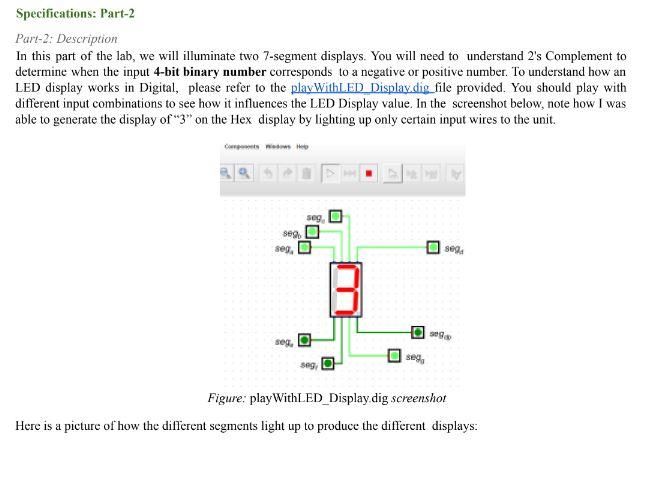
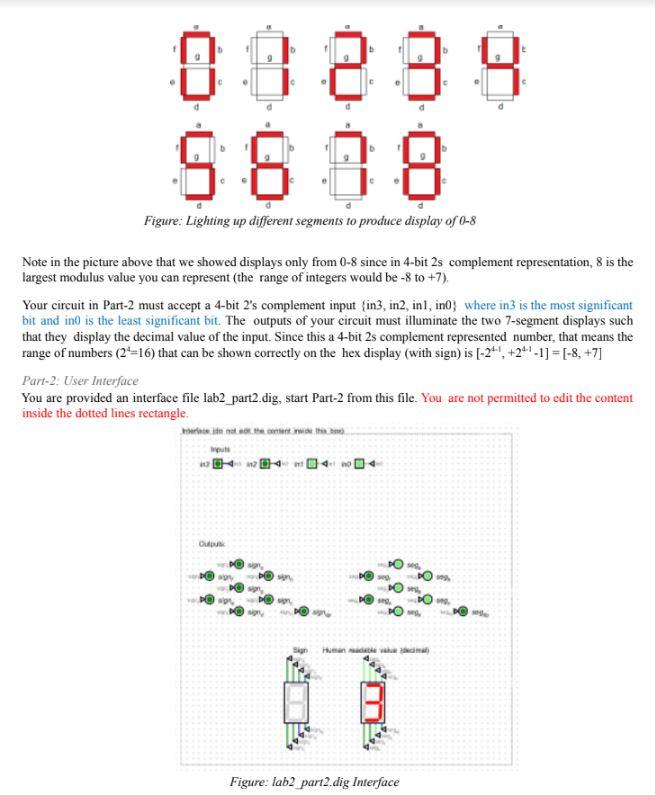
Specifications: Part-2 Part-2: Description In this part of the lab, we will illuminate two 7 -segment displays. You will need to understand 2 's Complement to determine when the input 4-bit binary number corresponds to a negative or positive number. To understand how an LED display works in Digital, please refer to the playWithLED Displaydig file provided. You should play with different input combinations to see how it influences the LED Display value. In the screenshot below, note how I was able to generate the display of "3" on the Hex display by lighting up only certain input wires to the unit. Figure: playWithLED_Displaydig screenshot Here is a picture of how the different segments light up to produce the different displays: Figure: Lighting up different segments to produce display of 08 Note in the picture above that we showed displays only from 08 since in 4-bit 2 s complement representation, 8 is the largest modulus value you can represent (the range of integers would be 8 to +7 ). Your circuit in Part-2 must accept a 4-bit 2's complement input \{in3, in2, in1, in0 } where in 3 is the most significant bit and in0 is the least significant bit. The outputs of your circuit must illuminate the two 7-segment displays such that they display the decimal value of the input. Since this a 4-bit 2s complement represented number, that means the range of numbers (24=16 ) that can be shown correctly on the hex display (with sign) is [241,+2411]=[8,+7] Part-2; User Interface You are provided an interface file lab2 part2.dig, start Part-2 from this file. You are not permitted to edit the content inside the dotted lines rectangle. Figure: lab2 part2.dig InterfaceStep by Step Solution
There are 3 Steps involved in it
Step: 1
Get Instant Access to Expert-Tailored Solutions
See step-by-step solutions with expert insights and AI powered tools for academic success
Step: 2
Step: 3
Ace Your Homework with AI
Get the answers you need in no time with our AI-driven, step-by-step assistance
Get Started