PLEASE HELP WITH THIS NETWORKING LAB PRACTISE
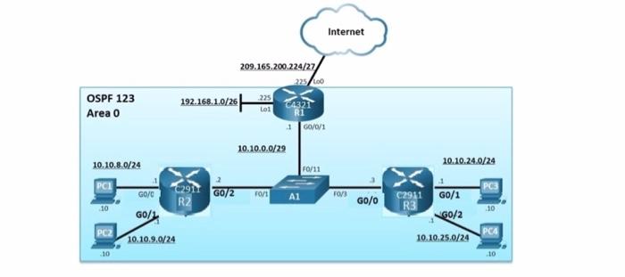
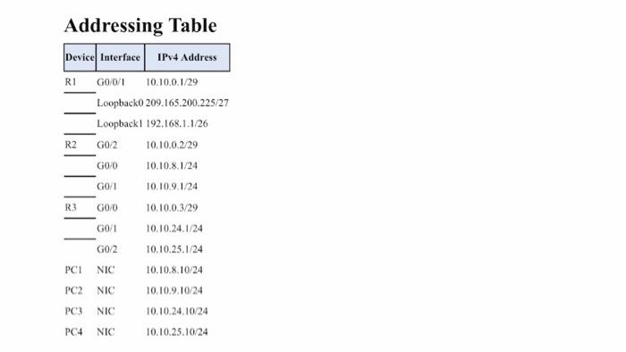
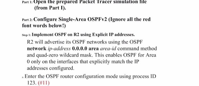
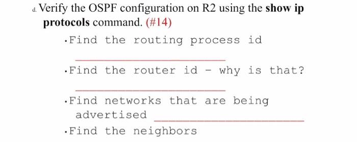
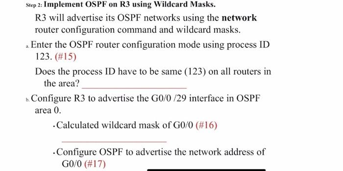
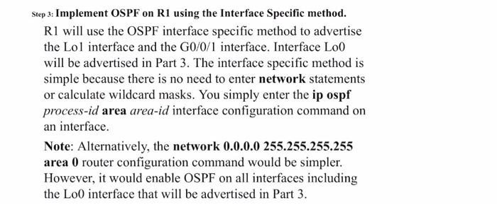
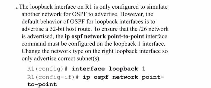
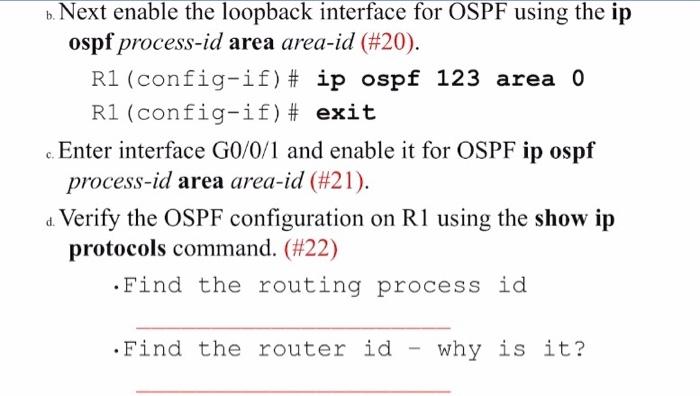
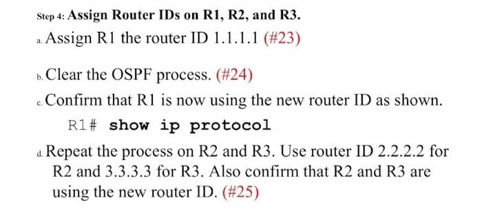
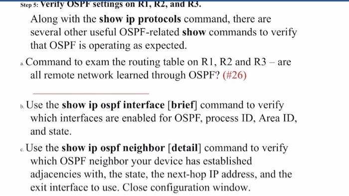
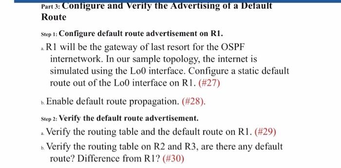
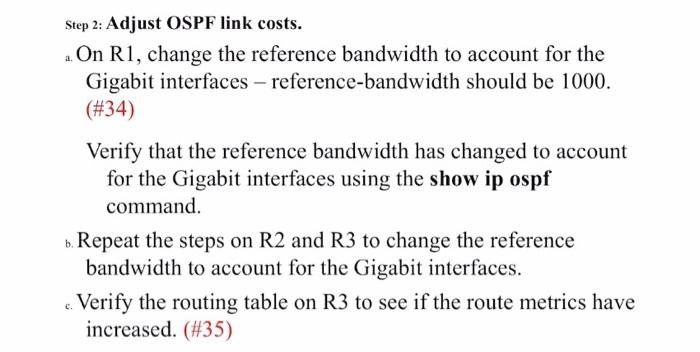
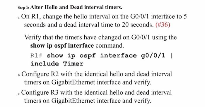
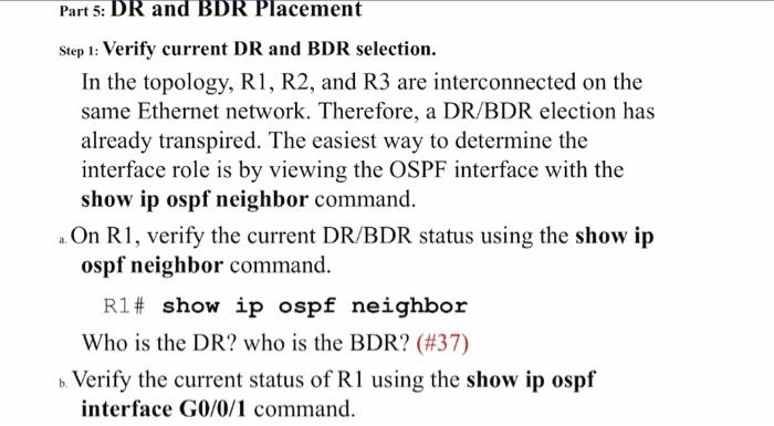
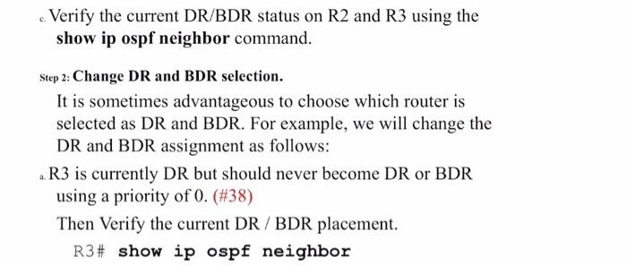
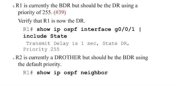
Addressino Table Part 1: Open the prepared Packet I racer simulation file (from Part I). Part 2: Configure Single-Area OSPFv2 (Ignore all the red font words below!) Step 1: Implement OSPF on R2 using Explicit IP addresses. R2 will advertise its OSPF networks using the OSPF network ip-address 0.0.0.0 area area-id command method and quad-zero wildcard mask. This enables OSPF for Area 0 only on the interfaces that explicitly match the IP addresses configured. a. Enter the OSPF router configuration mode using process ID 123. (\#11) b. Configure OSPF to advertise the network address of the G0/2 interface (i.e., 10.10.0.2) with the quad-zero mask. (\#12) c. Next, Configure OSPF to advertise the network address of G0/0 and G0/1 interfaces using a quad-zero mask. (\#13) These networks are now being advertised to other OSPF routers. d. Verify the OSPF configuration on R2 using the show ip protocols command. (\#14) - Find the routing process id -Find the router id - why is that? - Find networks that are being advertised - Find the neighbors Step 2: Implement OSPF on R3 using Wildcard Masks. R3 will advertise its OSPF networks using the network router configuration command and wildcard masks. a. Enter the OSPF router configuration mode using process ID 123. (\#15) Does the process ID have to be same (123) on all routers in the area? b. Configure R 3 to advertise the G0/0/29 interface in OSPF area 0. - Calculated wildcard mask of G0/0 (\#16) - Configure OSPF to advertise the network address of G0/0 (\#17) c. Configure R3 to advertise the two /24 networks in OSPF area 0 using two network statements with specific wildcard mask for each subnet. (\#18) d. Verify the OSPF configuration on R3 using the show ip protocols command. (\#19) Step 3: Implement OSPF on R1 using the Interface Specific method. R1 will use the OSPF interface specific method to advertise the Lol interface and the G0/0/1 interface. Interface Lo0 will be advertised in Part 3 . The interface specific method is simple because there is no need to enter network statements or calculate wildcard masks. You simply enter the ip ospf process-id area area-id interface configuration command on an interface. Note: Alternatively, the network 0.0.0.0255.255.255.255 area 0 router configuration command would be simpler. However, it would enable OSPF on all interfaces including the Lo0 interface that will be advertised in Part 3. The loopback interface on R1 is only configured to simulate another network for OSPF to advertise. However, the default behavior of OSPF for loopback interfaces is to advertise a 32-bit host route. To ensure that the /26 network is advertised, the ip ospf network point-to-point interface command must be configured on the loopback 1 interface. Change the network type on the right loopback interface so only advertise correct subnet(s). R1 (config) \# interface loopback 1 R1 (config-if) \# ip ospf network pointto-point b. Next enable the loopback interface for OSPF using the ip ospf process-id area area-id (\#20). R1 (config-if) \# ip ospf 123 area 0 R1 (config-if) \# exit c. Enter interface G0/0/1 and enable it for OSPF ip ospf process-id area area-id (\#21). d. Verify the OSPF configuration on R1 using the show ip protocols command. (\#22) - Find the routing process id -Find the router id - why is it? - Find networks that are being advertised . Find the neighbors Step 4: Assign Router IDs on R1, R2, and R3. a. Assign R1 the router ID 1.1.1.1 (\#23) b. Clear the OSPF process. (\#24) c. Confirm that R1 is now using the new router ID as shown. R1\# show ip protocol d. Repeat the process on R2 and R3. Use router ID 2.2.2.2 for R2 and 3.3.3.3 for R3. Also confirm that R2 and R3 are using the new router ID. (\#25) Along with the show ip protocols command, there are several other useful OSPF-related show commands to verify that OSPF is operating as expected. a. Command to exam the routing table on R1, R2 and R3 - are all remote network learned through OSPF? (\#26) b. Use the show ip ospf interface [brief] command to verify which interfaces are enabled for OSPF, process ID, Area ID, and state. c. Use the show ip ospf neighbor [detail] command to verify which OSPF neighbor your device has established adjacencies with, the state, the next-hop IP address, and the exit interface to use. Close configuration window. Part 3: Configure and Verify the Advertising of a Default Route Step 1: Configure default route advertisement on R1. a. R1 will be the gateway of last resort for the OSPF internetwork. In our sample topology, the internet is simulated using the Lo0 interface. Configure a static default route out of the Lo0 interface on R1. (\#27) b. Enable default route propagation. (\#28). Step 2: Verify the default route advertisement. a. Verify the routing table and the default route on R1. (\#29) b. Verify the routing table on R2 and R3, are there any default route? Difference from R1? (\#30) Part 4: Implement OSPF Network Optimizing Features Step 1: Configure passive interfaces on R1, R2 and R3. a. Configure R1 passive interface (\#31) Verify which interfaces are passive using the show ip protocols command. b. Configure and verify R2 passive interface(s) (\#32) c. Configure and verify R3 passive interfaces (\#33) Step 2: Adjust OSPF link costs. a. On R1, change the reference bandwidth to account for the Gigabit interfaces - reference-bandwidth should be 1000 . (#34) Verify that the reference bandwidth has changed to account for the Gigabit interfaces using the show ip ospf command. b. Repeat the steps on R2 and R3 to change the reference bandwidth to account for the Gigabit interfaces. c. Verify the routing table on R3 to see if the route metrics have increased. (\#35) Step 3: Alter Hello and Dead interval timers. a. On R1, change the hello interval on the G0/0/1 interface to 5 seconds and a dead interval time to 20 seconds. (\#36) Verify that the timers have changed on G0/0/1 using the show ip ospf interface command. R1\# show ip ospf interface g0/0/1 I include Timer b. Configure R2 with the identical hello and dead interval timers on GigabitEthernet interface and verify. c. Configure R3 with the identical hello and dead interval timers on GigabitEthernet interface and verify. Step 1: Verify current DR and BDR selection. In the topology, R1, R2, and R3 are interconnected on the same Ethernet network. Therefore, a DR/BDR election has already transpired. The easiest way to determine the interface role is by viewing the OSPF interface with the show ip ospf neighbor command. a. On R1, verify the current DR/BDR status using the show ip ospf neighbor command. R1\# show ip ospf neighbor Who is the DR? who is the BDR? (\#37) b. Verify the current status of R1 using the show ip ospf interface G0/0/1 command. c. Verify the current DR/BDR status on R2 and R3 using the show ip ospf neighbor command. Step 2: Change DR and BDR selection. It is sometimes advantageous to choose which router is selected as DR and BDR. For example, we will change the DR and BDR assignment as follows: a. R3 is currently DR but should never become DR or BDR using a priority of 0 . (\#38) Then Verify the current DR / BDR placement. R3\# show ip ospf neighbor b. R1 is currently the BDR but should be the DR using a priority of 255. (\#39) Verify that R1 is now the DR. R1\# show ip ospf interface g0/0/1 I include State Transmit Delay is 1sec, State DR, Priority 255 c. R2 is currently a DROTHER but should be the BDR using the default priority. R1\# show ip ospf neighbor Addressino Table Part 1: Open the prepared Packet I racer simulation file (from Part I). Part 2: Configure Single-Area OSPFv2 (Ignore all the red font words below!) Step 1: Implement OSPF on R2 using Explicit IP addresses. R2 will advertise its OSPF networks using the OSPF network ip-address 0.0.0.0 area area-id command method and quad-zero wildcard mask. This enables OSPF for Area 0 only on the interfaces that explicitly match the IP addresses configured. a. Enter the OSPF router configuration mode using process ID 123. (\#11) b. Configure OSPF to advertise the network address of the G0/2 interface (i.e., 10.10.0.2) with the quad-zero mask. (\#12) c. Next, Configure OSPF to advertise the network address of G0/0 and G0/1 interfaces using a quad-zero mask. (\#13) These networks are now being advertised to other OSPF routers. d. Verify the OSPF configuration on R2 using the show ip protocols command. (\#14) - Find the routing process id -Find the router id - why is that? - Find networks that are being advertised - Find the neighbors Step 2: Implement OSPF on R3 using Wildcard Masks. R3 will advertise its OSPF networks using the network router configuration command and wildcard masks. a. Enter the OSPF router configuration mode using process ID 123. (\#15) Does the process ID have to be same (123) on all routers in the area? b. Configure R 3 to advertise the G0/0/29 interface in OSPF area 0. - Calculated wildcard mask of G0/0 (\#16) - Configure OSPF to advertise the network address of G0/0 (\#17) c. Configure R3 to advertise the two /24 networks in OSPF area 0 using two network statements with specific wildcard mask for each subnet. (\#18) d. Verify the OSPF configuration on R3 using the show ip protocols command. (\#19) Step 3: Implement OSPF on R1 using the Interface Specific method. R1 will use the OSPF interface specific method to advertise the Lol interface and the G0/0/1 interface. Interface Lo0 will be advertised in Part 3 . The interface specific method is simple because there is no need to enter network statements or calculate wildcard masks. You simply enter the ip ospf process-id area area-id interface configuration command on an interface. Note: Alternatively, the network 0.0.0.0255.255.255.255 area 0 router configuration command would be simpler. However, it would enable OSPF on all interfaces including the Lo0 interface that will be advertised in Part 3. The loopback interface on R1 is only configured to simulate another network for OSPF to advertise. However, the default behavior of OSPF for loopback interfaces is to advertise a 32-bit host route. To ensure that the /26 network is advertised, the ip ospf network point-to-point interface command must be configured on the loopback 1 interface. Change the network type on the right loopback interface so only advertise correct subnet(s). R1 (config) \# interface loopback 1 R1 (config-if) \# ip ospf network pointto-point b. Next enable the loopback interface for OSPF using the ip ospf process-id area area-id (\#20). R1 (config-if) \# ip ospf 123 area 0 R1 (config-if) \# exit c. Enter interface G0/0/1 and enable it for OSPF ip ospf process-id area area-id (\#21). d. Verify the OSPF configuration on R1 using the show ip protocols command. (\#22) - Find the routing process id -Find the router id - why is it? - Find networks that are being advertised . Find the neighbors Step 4: Assign Router IDs on R1, R2, and R3. a. Assign R1 the router ID 1.1.1.1 (\#23) b. Clear the OSPF process. (\#24) c. Confirm that R1 is now using the new router ID as shown. R1\# show ip protocol d. Repeat the process on R2 and R3. Use router ID 2.2.2.2 for R2 and 3.3.3.3 for R3. Also confirm that R2 and R3 are using the new router ID. (\#25) Along with the show ip protocols command, there are several other useful OSPF-related show commands to verify that OSPF is operating as expected. a. Command to exam the routing table on R1, R2 and R3 - are all remote network learned through OSPF? (\#26) b. Use the show ip ospf interface [brief] command to verify which interfaces are enabled for OSPF, process ID, Area ID, and state. c. Use the show ip ospf neighbor [detail] command to verify which OSPF neighbor your device has established adjacencies with, the state, the next-hop IP address, and the exit interface to use. Close configuration window. Part 3: Configure and Verify the Advertising of a Default Route Step 1: Configure default route advertisement on R1. a. R1 will be the gateway of last resort for the OSPF internetwork. In our sample topology, the internet is simulated using the Lo0 interface. Configure a static default route out of the Lo0 interface on R1. (\#27) b. Enable default route propagation. (\#28). Step 2: Verify the default route advertisement. a. Verify the routing table and the default route on R1. (\#29) b. Verify the routing table on R2 and R3, are there any default route? Difference from R1? (\#30) Part 4: Implement OSPF Network Optimizing Features Step 1: Configure passive interfaces on R1, R2 and R3. a. Configure R1 passive interface (\#31) Verify which interfaces are passive using the show ip protocols command. b. Configure and verify R2 passive interface(s) (\#32) c. Configure and verify R3 passive interfaces (\#33) Step 2: Adjust OSPF link costs. a. On R1, change the reference bandwidth to account for the Gigabit interfaces - reference-bandwidth should be 1000 . (#34) Verify that the reference bandwidth has changed to account for the Gigabit interfaces using the show ip ospf command. b. Repeat the steps on R2 and R3 to change the reference bandwidth to account for the Gigabit interfaces. c. Verify the routing table on R3 to see if the route metrics have increased. (\#35) Step 3: Alter Hello and Dead interval timers. a. On R1, change the hello interval on the G0/0/1 interface to 5 seconds and a dead interval time to 20 seconds. (\#36) Verify that the timers have changed on G0/0/1 using the show ip ospf interface command. R1\# show ip ospf interface g0/0/1 I include Timer b. Configure R2 with the identical hello and dead interval timers on GigabitEthernet interface and verify. c. Configure R3 with the identical hello and dead interval timers on GigabitEthernet interface and verify. Step 1: Verify current DR and BDR selection. In the topology, R1, R2, and R3 are interconnected on the same Ethernet network. Therefore, a DR/BDR election has already transpired. The easiest way to determine the interface role is by viewing the OSPF interface with the show ip ospf neighbor command. a. On R1, verify the current DR/BDR status using the show ip ospf neighbor command. R1\# show ip ospf neighbor Who is the DR? who is the BDR? (\#37) b. Verify the current status of R1 using the show ip ospf interface G0/0/1 command. c. Verify the current DR/BDR status on R2 and R3 using the show ip ospf neighbor command. Step 2: Change DR and BDR selection. It is sometimes advantageous to choose which router is selected as DR and BDR. For example, we will change the DR and BDR assignment as follows: a. R3 is currently DR but should never become DR or BDR using a priority of 0 . (\#38) Then Verify the current DR / BDR placement. R3\# show ip ospf neighbor b. R1 is currently the BDR but should be the DR using a priority of 255. (\#39) Verify that R1 is now the DR. R1\# show ip ospf interface g0/0/1 I include State Transmit Delay is 1sec, State DR, Priority 255 c. R2 is currently a DROTHER but should be the BDR using the default priority. R1\# show ip ospf neighbor
