

Answered step by step
Verified Expert Solution
Question
1 Approved Answer
Please include all calculations and graphs. Do not just leave a formula or write an answer without calculations. If you are not going to do
Please include all calculations and graphs. Do not just leave a formula or write an answer without calculations. If you are not going to do these, please do not answer this question. This question is related to the field of Control engineering
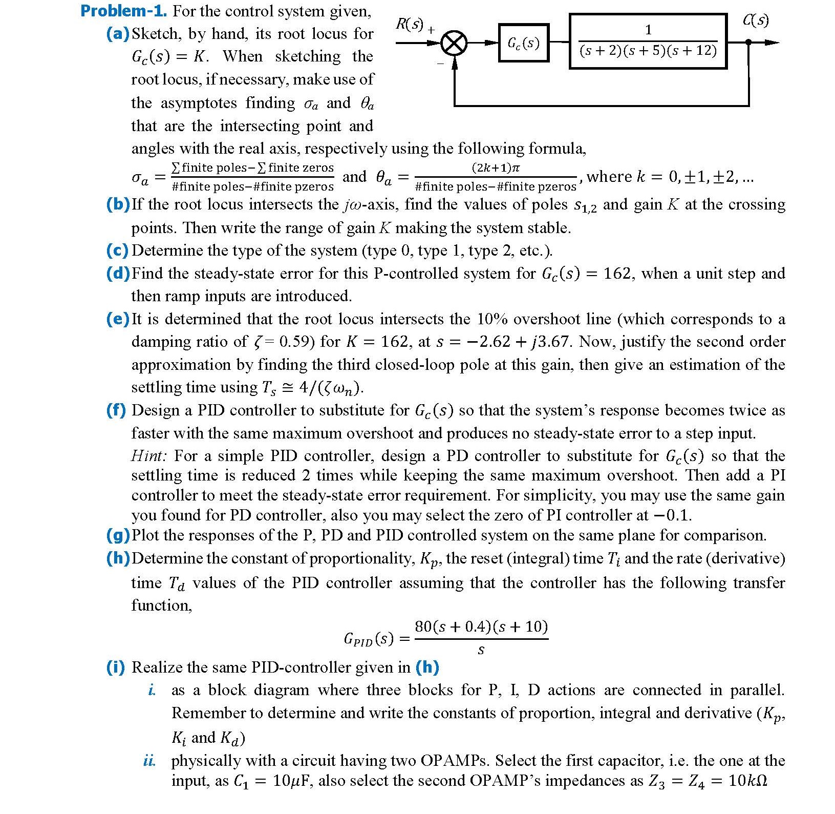
Problem For the control system given,
a Sketch, by hand, its root locus for
When sketching the
root locus, if necessary, make use of
the asymptotes finding and
that are the intersecting point and
angles with the real axis, respectively using the following formula,
and where dots
b If the root locus intersects the axis, find the values of poles and gain at the crossing
points. Then write the range of gain making the system stable.
c Determine the type of the system type type type etc.
dFind the steadystate error for this Pcontrolled system for when a unit step and
then ramp inputs are introduced.
e It is determined that the root locus intersects the overshoot line which corresponds to a
damping ratio of for at Now, justify the second order
approximation by finding the third closedloop pole at this gain, then give an estimation of the
settling time using ~
f Design a PID controller to substitute for so that the system's response becomes twice as
faster with the same maximum overshoot and produces no steadystate error to a step input.
Hint: For a simple PID controller, design a PD controller to substitute for so that the
settling time is reduced times while keeping the same maximum overshoot. Then add a PI
controller to meet the steadystate error requirement. For simplicity, you may use the same gain
you found for PD controller, also you may select the zero of PI controller at
gPlot the responses of the P PD and PID controlled system on the same plane for comparison.
h Determine the constant of proportionality, the reset integral time and the rate derivative
time values of the PID controller assuming that the controller has the following transfer
function,
i Realize the same PIDcontroller given in h
i as a block diagram where three blocks for P I, D actions are connected in parallel.
Remember to determine and write the constants of proportion, integral and derivative
and
ii physically with a circuit having two OPAMPs. Select the first capacitor, ie the one at the
input, as also select the second OPAMP's impedances as NOTE:NNN
Step by Step Solution
There are 3 Steps involved in it
Step: 1

Get Instant Access to Expert-Tailored Solutions
See step-by-step solutions with expert insights and AI powered tools for academic success
Step: 2

Step: 3
Ace Your Homework with AI
Get the answers you need in no time with our AI-driven, step-by-step assistance
Get Started
Vector Mechanics For Engineers Statics
Authors: R.C.Hibbeler
7th Edition
978-0072931105, 0072931108