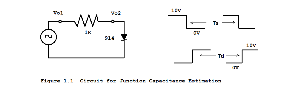
PLEASE JUST SIMULATE ACTIVITY 1 IN PSPICE OR MULTISIM


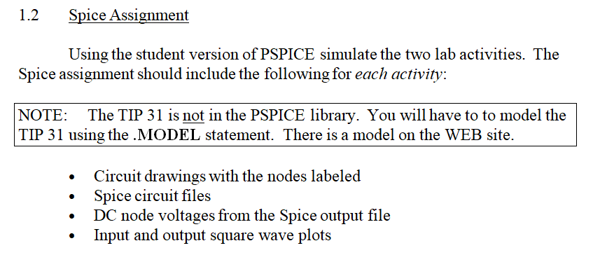
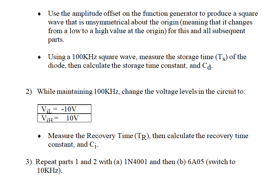
1.2 Spice Assignment Using the student version of PSPICE simulate the two lab activities. The Spice assignment should include the following for each activity: NOTE: The TIP 31 is not in the PSPICE library. You will have to to model the TIP 31 using the .MODEL statement. There is a model on the WEB site. Circuit drawings with the nodes labeled Spice circuit files DC node voltages from the Spice output file . Iput and output square wave plots Use the amplitude offset on the function generator to produce a square wave that is unsymmetrical about the origin (meaning that it changes from a low to a high value at the origin) for this and all subsequent parts. Using a 100KHz square wave, measure the storage time (Ts) of the diode, then calculate the storage time constant, and Cd 2) While maintaining 100KHz, change the voltage levels in the circuit to: Vi10V Measure the Recovery Time (TR), then calculate the recovery time constant, and Ci 3) Repeat parts 1 and 2 with (a) N4001 and then (b) 6A05 (switch to 10KHz). 10V Vol Vo2 @ 1K 914 10V 0V Figure 1.1 Circuit for Junction Capacitance Estimation 1.2 Spice Assignment Using the student version of PSPICE simulate the two lab activities. The Spice assignment should include the following for each activity: NOTE: The TIP 31 is not in the PSPICE library. You will have to to model the TIP 31 using the .MODEL statement. There is a model on the WEB site. Circuit drawings with the nodes labeled Spice circuit files DC node voltages from the Spice output file . Iput and output square wave plots Use the amplitude offset on the function generator to produce a square wave that is unsymmetrical about the origin (meaning that it changes from a low to a high value at the origin) for this and all subsequent parts. Using a 100KHz square wave, measure the storage time (Ts) of the diode, then calculate the storage time constant, and Cd 2) While maintaining 100KHz, change the voltage levels in the circuit to: Vi10V Measure the Recovery Time (TR), then calculate the recovery time constant, and Ci 3) Repeat parts 1 and 2 with (a) N4001 and then (b) 6A05 (switch to 10KHz). 10V Vol Vo2 @ 1K 914 10V 0V Figure 1.1 Circuit for Junction Capacitance Estimation


