

Answered step by step
Verified Expert Solution
Question
1 Approved Answer
Please provide ALU code and output the result into 7 segment display with an active low. Thank you. 1. Objectives The purpose of this laboratory
Please provide ALU code and output the result into 7 segment display with an active low. Thank you.
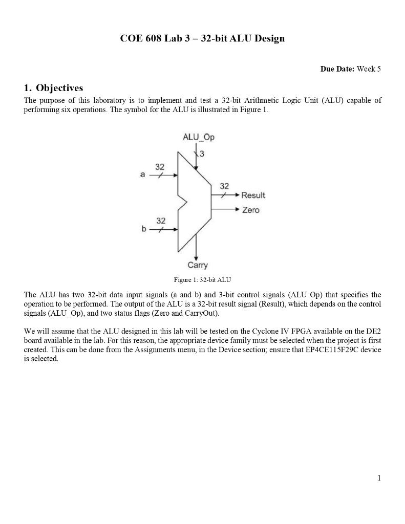
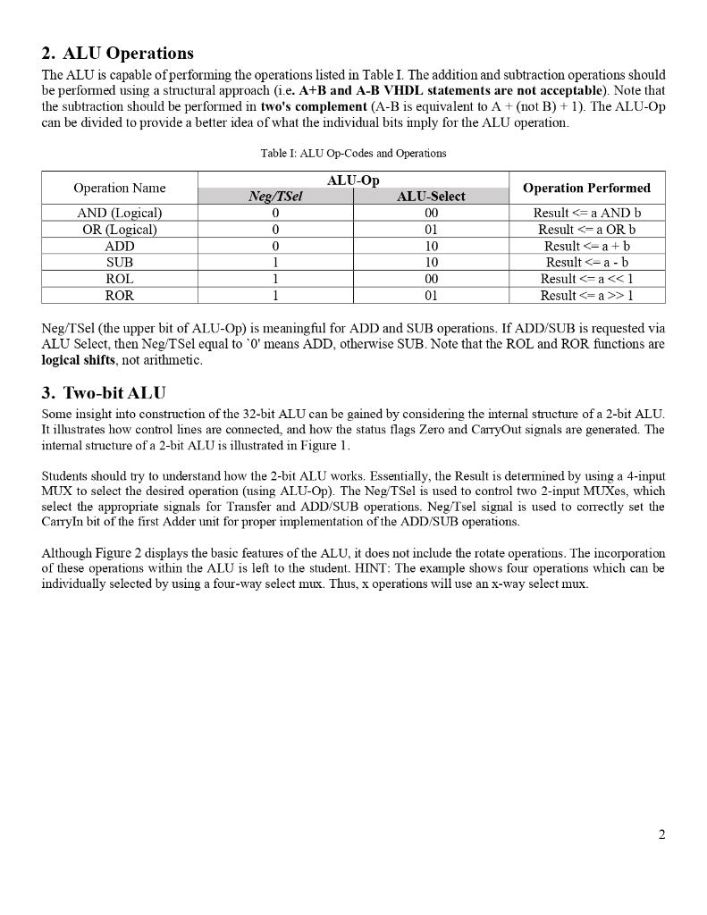
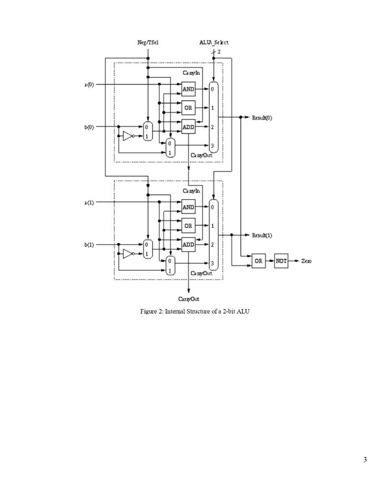
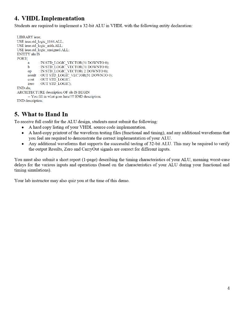
1. Objectives The purpose of this laboratory is to implement and test a 32-bit Arithmetic Logic Unit (ALU) capable of performing six operations. The symbol for the ALU is illustrated in Figure 1. The ALU has two 32-bit data input signals (a and b) and 3-bit control signals (ALU Op) that specifies the operation to be performed. The output of the ALU is a 32-bit result signal (Result), which depends on the control signals (ALU_Op), and two status flags (Zero and CarryOut). We will assume that the ALU designed in this lab will be tested on the Cyclone IV FPGA available on the DE2 board available in the lab. For this reason, the appropriate device family must be selected when the project is first created. This can be done from the Assignments menu, in the Device section; ensure that EP4CE115F29C device is selected. 2. ALU Operations The ALU is capable of performing the operations listed in Table I. The addition and subtraction operations should be performed using a structural approach (i.e. A+B and A-B VHDL statements are not acceptable). Note that the subtraction should be performed in two's complement (A-B is equivalent to A + (not B) + 1). The ALU-Op can be divided to provide a better idea of what the individual bits imply for the ALU operation. Table I: ALU Op-Codes and Operations Neg/TSel (the upper bit of ALU-Op) is meaningful for ADD and SUB operations. If ADD/SUB is requested via ALU Select, then Neg/TSel equal to ' 0 ' means ADD, otherwise SUB. Note that the ROL and ROR functions are logical shifts, not arithmetic. 3. Two-bit ALU Some insight into construction of the 32 -bit ALU can be gained by considering the internal structure of a 2-bit ALU. It illustrates how control lines are connected, and how the status flags Zero and CarryOut signals are generated. The internal structure of a 2-bit ALU is illustrated in Figure 1. Students should try to understand how the 2-bit ALU works. Essentially, the Result is determined by using a 4-input MUX to select the desired operation (using ALU-Op). The Neg/TSel is used to control two 2-input MUXes, which select the appropriate signals for Transfer and ADD/SUB operations. Neg/Tsel signal is used to correctly set the CarryIn bit of the first Adder unit for proper implementation of the ADD/SUB operations. Although Figure 2 displays the basic features of the ALU, it does not include the rotate operations. The incorporation of these operations within the ALU is left to the student. HINT: The example shows four operations which can be individually selected by using a four-way select mux. Thus, x operations will use an x-way select mux. Figure 2: Internal Structure of a 2-bit ALU 4. VHDL Implementation Students are required to implement a 32-bit ALU in VHDL with the following entity declaration: LIBRARY iee: USE ieee.std_logic_1164.ALL. USE ieee.stdlogic_arith_ALL: USE ieee.std_logic_unsigned.ALL: ENTITY alu IS PORTC \( \begin{array}{ll}\text { a } & \text { NNSTD_LOGIC_VECTOR(31 DOWNTO 0); } \\ \text { b } & \text { IN STDLLOGIC-VECTOR(3 I DOWNTO 0); } \\ \text { op } & \text { INSTD_LOGIC_VECTOR( } 2 \text { DOWNTO } 0) ; \\ \text { result } & \text { OUT STD_LOGIC-VECTOR }(31 \text { DOWNTO 0); } \\ \text { cout } & \text { OUT STD_LOGIC; } \\ \text { zero } & \text { OUT STD LOGIC); }\end{array} \) END alu, ARCHITECTURE description OF alu IS BEGIN -- You fill in what goes here!!!! END description, END description: 5. What to Hand In To receive full credit for the ALU design, students must submit the following: - A hard copy listing of your VHDL source code implementation. - A hard-copy printout of the waveform testing files (functional and timing), and any additional waveforms that you feel are required to demonstrate the correct implementation of your ALU. - Any additional wavefoms that supports the successful testing of 32 -bit ALU. This may be required to verify the output Results, Zero and CarryOut signals are correct for different inputs. You must also submit a short report (1-page) describing the timing characteristics of your ALU, meaning worst-case delays for the various inputs and operations (based on the characteristics of your ALU during your functional and timing simulations). Your lab instructor may also quiz you at the time of this demoStep by Step Solution
There are 3 Steps involved in it
Step: 1

Get Instant Access to Expert-Tailored Solutions
See step-by-step solutions with expert insights and AI powered tools for academic success
Step: 2

Step: 3
Ace Your Homework with AI
Get the answers you need in no time with our AI-driven, step-by-step assistance
Get Started
Advances In Databases And Information Systems 22nd European Conference Adbis 2018 Budapest Hungary September 2 5 2018 Proceedings Lncs 11019
Authors: Andras Benczur ,Bernhard Thalheim ,Tomas Horvath
1st Edition
3319983970, 978-3319983974