 please read carefully and each exercise is its own code. start with .orig x3000
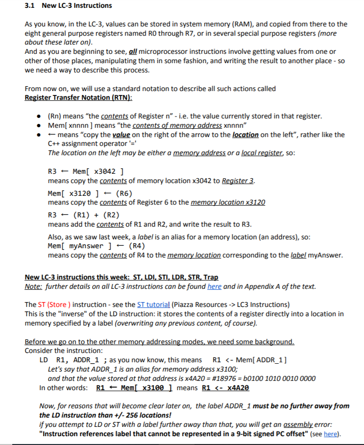
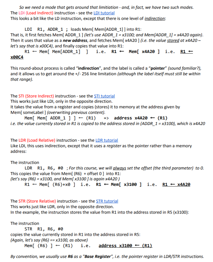
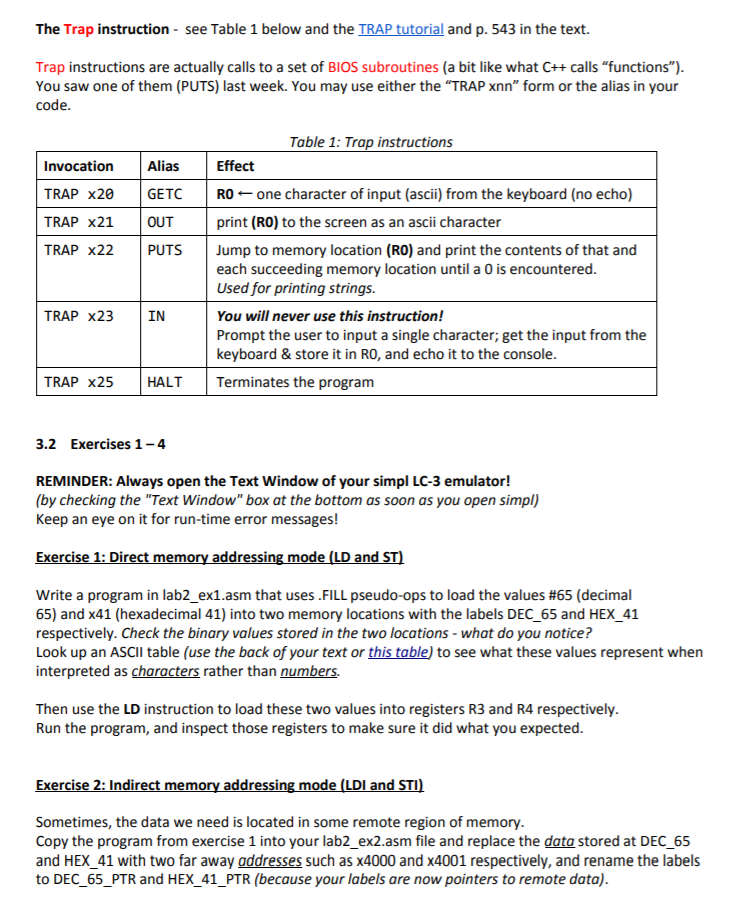
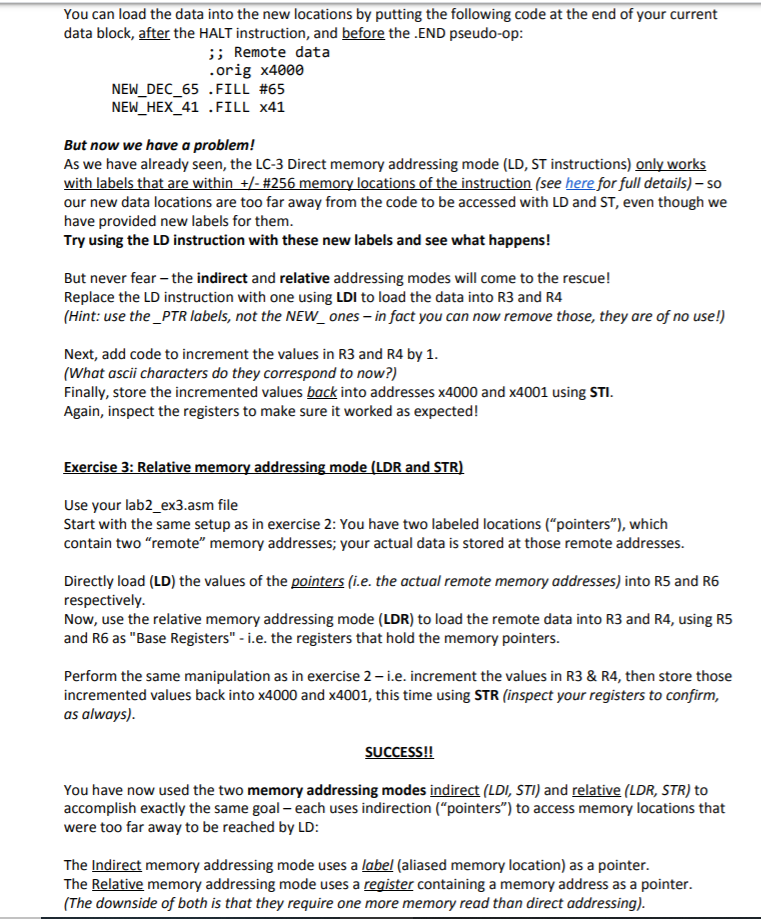
3.1 New LC-3 Instructions As you know, in the LC-3, values can be stored in system memory (RAM), and copied from there to the eight general purpose registers named RO through R7, or in several special purpose registers (more about these later on). And as you are beginning to see, all microprocessor instructions involve getting values from one or other of those places, manipulating them in some fashion, and writing the result to another place - so we need a way to describe this process. From now on, we will use a standard notation to describe all such actions called Register Transfer Notation (RTN): (Rn) means "the contents of Register n" - i.e. the value currently stored in that register. Mem[ xnnnn) means "the contents of memory address xnnnn" means "copy the value on the right of the arrow to the location on the left", rather like the C++ assignment operator'' The location on the left may be either a memory address or a local register, so: R3 Mem[ x30421 means copy the contents of memory location x3042 to Register 3. Mem[ x3120 ] - (R6) means copy the contents of Register 6 to the memory location x3120 R3 (R1) + (R2) means add the contents of R1 and R2, and write the result to R3. Also, as we saw last week, a label is an alias for a memory location (an address), so: Mem[ myAnswer ] - (R4) means copy the contents of R4 to the memory location corresponding to the label myAnswer. New LC-3 instructions this week: ST, LDI, STI, LDR, STR, Trap Note: further details on all LC-3 instructions can be found here and in Appendix A of the text. The ST (Store ) instruction - see the ST tutorial (Piazza Resources -> LC3 Instructions) This is the "inverse" of the LD instruction: it stores the contents of a register directly into a location in memory specified by a label (overwriting any previous content, of course). Before we go on to the other memory addressing modes, we need some background. Consider the instruction LD R1, ADDR_1 ; as you now know, this means R1 address x4420 (R1) i.e. the value currently stored in R1 is copied to the address stored in (ADDR_1 = x3100), which is x4A20 The LDR (Load Relative) instruction - see the LDR tutorial Like LDI, this uses indirection, except that it uses a register as the pointer rather than a memory address: The instruction LDR R1, R6, #0 ; For this course, we will always set the offset (the third parameter) to 0. This copies the value from Mem[ (R6) + offset 0 ] into R1: (let's say (R6) = x3100, and Mem[x3100 ) is again x4A20 ) R1 - Mem[ (R6)+x0 ] i.e. R1 + Mem[ x3100 ] i.e. R1 + x4A20 The STR (Store Relative) instruction - see the STR tutorial This works just like LDR, only in the opposite direction. In the example, the instruction stores the value from R1 into the address stored in R5 (x3100): The instruction STR R1, R6, #0 copies the value currently stored in R1 into the address stored in R5: (Again, let's say (R6) == x3100, as above) Mem[ (R6) ] = (R1) i.e. address X3100 + (R1) By convention, we usually use R6 as a "Base Register", i.e. the pointer register in LDR/STR instructions. The Trap instruction - see Table 1 below and the TRAP tutorial and p. 543 in the text. Trap instructions are actually calls to a set of BIOS subroutines (a bit like what C++ calls "functions"). You saw one of them (PUTS) last week. You may use either the "TRAP xnn" form or the alias in your code. Invocation TRAP X20 Alias GETC TRAP x21 TRAP X22 OUT PUTS Table 1: Trap instructions Effect RO - one character of input (ascii) from the keyboard (no echo) print (RO) to the screen as an ascii character Jump to memory location (RO) and print the contents of that and each succeeding memory location until a 0 is encountered. Used for printing strings. TRAP x23 IN You will never use this instruction! Prompt the user to input a single character; get the input from the keyboard & store it in RO, and echo it to the console. Terminates the program TRAP X25 HALT 3.2 Exercises 1-4 REMINDER: Always open the Text Window of your simpl LC-3 emulator! (by checking the "Text Window" box at the bottom as soon as you open simpl) Keep an eye on it for run-time error messages! Exercise 1: Direct memory addressing mode (LD and ST) Write a program in lab2 ex1.asm that uses .FILL pseudo-ops to load the values #65 (decimal 65) and x41 (hexadecimal 41) into two memory locations with the labels DEC_65 and HEX_41 respectively. Check the binary values stored in the two locations - what do you notice? Look up an ASCII table (use the back of your text or this table) to see what these values represent when interpreted as characters rather than numbers. Then use the LD instruction to load these two values into registers R3 and R4 respectively. Run the program, and inspect those registers to make sure it did what you expected. Exercise 2: Indirect memory addressing mode (LDI and STI) Sometimes, the data we need is located in some remote region of memory. Copy the program from exercise 1 into your lab2_ex2.asm file and replace the data stored at DEC_65 and HEX 41 with two far away addresses such as X4000 and X4001 respectively, and rename the labels to DEC 65 PTR and HEX_41_PTR (because your labels are now pointers to remote data). You can load the data into the new locations by putting the following code at the end of your current data block, after the HALT instruction, and before the .END pseudo-op: ;; Remote data .orig x4000 NEW_DEC_65 .FILL #65 NEW_HEX_41 .FILL x41 But now we have a problem! As we have already seen, the LC-3 Direct memory addressing mode (LD, ST instructions) only works with labels that are within +/- #256 memory locations of the instruction (see here for full details) - so our new data locations are too far away from the code to be accessed with LD and ST, even though we have provided new labels for them. Try using the LD instruction with these new labels and see what happens! But never fear - the indirect and relative addressing modes will come to the rescue! Replace the LD instruction with one using LDI to load the data into R3 and R4 (Hint: use the _PTR labels, not the NEW_ones - in fact you can now remove those, they are of no use!) Next, add code to increment the values in R3 and R4 by 1. (What ascii characters do they correspond to now?) Finally, store the incremented values back into addresses 4000 and x4001 using STI. Again, inspect the registers to make sure it worked as expected! Exercise 3: Relative memory addressing mode (LDR and STR) Use your lab2_ex3.asm file Start with the same setup as in exercise 2: You have two labeled locations ("pointers"), which contain two "remote" memory addresses; your actual data is stored at those remote addresses. Directly load (LD) the values of the pointers (i.e. the actual remote memory addresses) into R5 and R6 respectively. Now, use the relative memory addressing mode (LDR) to load the remote data into R3 and R4, using R5 and R6 as "Base Registers" - i.e. the registers that hold the memory pointers. Perform the same manipulation as in exercise 2- i.e. increment the values in R3 & R4, then store those incremented values back into X4000 and x4001, this time using STR (inspect your registers to confirm, as always). SUCCESS!! You have now used the two memory addressing modes indirect (LDI, STI) and relative (LDR, STR) to accomplish exactly the same goal - each uses indirection ("pointers") to access memory locations that were too far away to be reached by LD: The Indirect memory addressing mode uses a label (aliased memory location) as a pointer. The Relative memory addressing mode uses a register containing a memory address as a pointer. (The downside of both is that they require one more memory read than direct addressing). Exercise 4: Loops Use the conditional branch instruction (BR) to construct a counter-controlled loop (the same control structure you learned in lab 1 and assn 1) Hard-code (i.e. use .FILL) local data values x61 and x1A, and load them into RO and R1 respectively. Inside a loop, output to console the contents of RO as an ascii character (Trap x21, or OUT), then immediately increment RO by 1. Use R1 as the loop counter by decrementing it by 1 each iteration, just as you did in lab 1-i.e. the loop should be executed exactly x1A times. Think carefully about how and when to terminate the loop: do you use BRn or BRnz or BRz or BRzp or ?? What does this loop do? Can you figure it out before you run it? 3.1 New LC-3 Instructions As you know, in the LC-3, values can be stored in system memory (RAM), and copied from there to the eight general purpose registers named RO through R7, or in several special purpose registers (more about these later on). And as you are beginning to see, all microprocessor instructions involve getting values from one or other of those places, manipulating them in some fashion, and writing the result to another place - so we need a way to describe this process. From now on, we will use a standard notation to describe all such actions called Register Transfer Notation (RTN): (Rn) means "the contents of Register n" - i.e. the value currently stored in that register. Mem[ xnnnn) means "the contents of memory address xnnnn" means "copy the value on the right of the arrow to the location on the left", rather like the C++ assignment operator'' The location on the left may be either a memory address or a local register, so: R3 Mem[ x30421 means copy the contents of memory location x3042 to Register 3. Mem[ x3120 ] - (R6) means copy the contents of Register 6 to the memory location x3120 R3 (R1) + (R2) means add the contents of R1 and R2, and write the result to R3. Also, as we saw last week, a label is an alias for a memory location (an address), so: Mem[ myAnswer ] - (R4) means copy the contents of R4 to the memory location corresponding to the label myAnswer. New LC-3 instructions this week: ST, LDI, STI, LDR, STR, Trap Note: further details on all LC-3 instructions can be found here and in Appendix A of the text. The ST (Store ) instruction - see the ST tutorial (Piazza Resources -> LC3 Instructions) This is the "inverse" of the LD instruction: it stores the contents of a register directly into a location in memory specified by a label (overwriting any previous content, of course). Before we go on to the other memory addressing modes, we need some background. Consider the instruction LD R1, ADDR_1 ; as you now know, this means R1 address x4420 (R1) i.e. the value currently stored in R1 is copied to the address stored in (ADDR_1 = x3100), which is x4A20 The LDR (Load Relative) instruction - see the LDR tutorial Like LDI, this uses indirection, except that it uses a register as the pointer rather than a memory address: The instruction LDR R1, R6, #0 ; For this course, we will always set the offset (the third parameter) to 0. This copies the value from Mem[ (R6) + offset 0 ] into R1: (let's say (R6) = x3100, and Mem[x3100 ) is again x4A20 ) R1 - Mem[ (R6)+x0 ] i.e. R1 + Mem[ x3100 ] i.e. R1 + x4A20 The STR (Store Relative) instruction - see the STR tutorial This works just like LDR, only in the opposite direction. In the example, the instruction stores the value from R1 into the address stored in R5 (x3100): The instruction STR R1, R6, #0 copies the value currently stored in R1 into the address stored in R5: (Again, let's say (R6) == x3100, as above) Mem[ (R6) ] = (R1) i.e. address X3100 + (R1) By convention, we usually use R6 as a "Base Register", i.e. the pointer register in LDR/STR instructions. The Trap instruction - see Table 1 below and the TRAP tutorial and p. 543 in the text. Trap instructions are actually calls to a set of BIOS subroutines (a bit like what C++ calls "functions"). You saw one of them (PUTS) last week. You may use either the "TRAP xnn" form or the alias in your code. Invocation TRAP X20 Alias GETC TRAP x21 TRAP X22 OUT PUTS Table 1: Trap instructions Effect RO - one character of input (ascii) from the keyboard (no echo) print (RO) to the screen as an ascii character Jump to memory location (RO) and print the contents of that and each succeeding memory location until a 0 is encountered. Used for printing strings. TRAP x23 IN You will never use this instruction! Prompt the user to input a single character; get the input from the keyboard & store it in RO, and echo it to the console. Terminates the program TRAP X25 HALT 3.2 Exercises 1-4 REMINDER: Always open the Text Window of your simpl LC-3 emulator! (by checking the "Text Window" box at the bottom as soon as you open simpl) Keep an eye on it for run-time error messages! Exercise 1: Direct memory addressing mode (LD and ST) Write a program in lab2 ex1.asm that uses .FILL pseudo-ops to load the values #65 (decimal 65) and x41 (hexadecimal 41) into two memory locations with the labels DEC_65 and HEX_41 respectively. Check the binary values stored in the two locations - what do you notice? Look up an ASCII table (use the back of your text or this table) to see what these values represent when interpreted as characters rather than numbers. Then use the LD instruction to load these two values into registers R3 and R4 respectively. Run the program, and inspect those registers to make sure it did what you expected. Exercise 2: Indirect memory addressing mode (LDI and STI) Sometimes, the data we need is located in some remote region of memory. Copy the program from exercise 1 into your lab2_ex2.asm file and replace the data stored at DEC_65 and HEX 41 with two far away addresses such as X4000 and X4001 respectively, and rename the labels to DEC 65 PTR and HEX_41_PTR (because your labels are now pointers to remote data). You can load the data into the new locations by putting the following code at the end of your current data block, after the HALT instruction, and before the .END pseudo-op: ;; Remote data .orig x4000 NEW_DEC_65 .FILL #65 NEW_HEX_41 .FILL x41 But now we have a problem! As we have already seen, the LC-3 Direct memory addressing mode (LD, ST instructions) only works with labels that are within +/- #256 memory locations of the instruction (see here for full details) - so our new data locations are too far away from the code to be accessed with LD and ST, even though we have provided new labels for them. Try using the LD instruction with these new labels and see what happens! But never fear - the indirect and relative addressing modes will come to the rescue! Replace the LD instruction with one using LDI to load the data into R3 and R4 (Hint: use the _PTR labels, not the NEW_ones - in fact you can now remove those, they are of no use!) Next, add code to increment the values in R3 and R4 by 1. (What ascii characters do they correspond to now?) Finally, store the incremented values back into addresses 4000 and x4001 using STI. Again, inspect the registers to make sure it worked as expected! Exercise 3: Relative memory addressing mode (LDR and STR) Use your lab2_ex3.asm file Start with the same setup as in exercise 2: You have two labeled locations ("pointers"), which contain two "remote" memory addresses; your actual data is stored at those remote addresses. Directly load (LD) the values of the pointers (i.e. the actual remote memory addresses) into R5 and R6 respectively. Now, use the relative memory addressing mode (LDR) to load the remote data into R3 and R4, using R5 and R6 as "Base Registers" - i.e. the registers that hold the memory pointers. Perform the same manipulation as in exercise 2- i.e. increment the values in R3 & R4, then store those incremented values back into X4000 and x4001, this time using STR (inspect your registers to confirm, as always). SUCCESS!! You have now used the two memory addressing modes indirect (LDI, STI) and relative (LDR, STR) to accomplish exactly the same goal - each uses indirection ("pointers") to access memory locations that were too far away to be reached by LD: The Indirect memory addressing mode uses a label (aliased memory location) as a pointer. The Relative memory addressing mode uses a register containing a memory address as a pointer. (The downside of both is that they require one more memory read than direct addressing). Exercise 4: Loops Use the conditional branch instruction (BR) to construct a counter-controlled loop (the same control structure you learned in lab 1 and assn 1) Hard-code (i.e. use .FILL) local data values x61 and x1A, and load them into RO and R1 respectively. Inside a loop, output to console the contents of RO as an ascii character (Trap x21, or OUT), then immediately increment RO by 1. Use R1 as the loop counter by decrementing it by 1 each iteration, just as you did in lab 1-i.e. the loop should be executed exactly x1A times. Think carefully about how and when to terminate the loop: do you use BRn or BRnz or BRz or BRzp or ?? What does this loop do? Can you figure it out before you run it