Question: please solve all question by usig matlab thank you. LCEV Tuys 20 C UUUULUUII IU LUV Ul.walceu LIVIUVIES WILL . II: The Discrete Fourier Transform


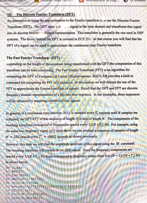
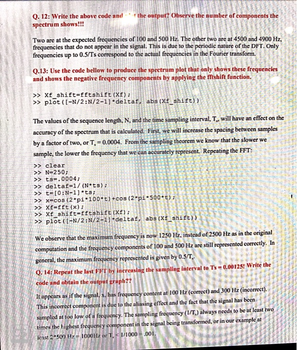
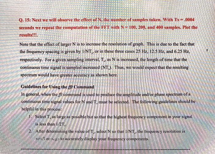
LCEV Tuys 20 C UUUULUUII IU LUV Ul.walceu LIVIUVIES WILL . II: The Discrete Fourier Transform (DFT) An alternative to using the approximation to the Fourier transform is to use the Discrete Fourier Transform (DFT). The DFT takes a di signal in the time domain and transforms that signal into its discrete frequen domain representation. This transform is generally the one used in DSP systems. The theory behind the DFT is covered in ECE 351. In that course you will find that the DFT of a signal can be used to approximate the continuous time Fourier transform. The Fast Fourier Transform (FFT) Lepending on the length of the sequence being transformed with the DFT the computation of this transform can be time consuming. The Fast Fourier Transform (FFT) is an algorithm for computing the DFT of a sequence in a more efficient manner. MATLAB provides a built in command for computing the FFT of a sequence. In this section we will discuss the use of the FFT to approximate the Fourier transform of signals. Recall that the DFT and FFT are discrete frequency domain representations of a discrete time sequence. In our examples, these sequences will be obtained by sampling continuous time signals. In general, if a continuous time function, X(t), is sampled every T, seconds until samples are collected, the DFT/EFT of this sequence of length N is also of length N. The components of the resulting transform correspond to frequencies spaced every 1/( N T) Hz. For example, using the same two-frequency signal X(t) used above we can produce a sequence of samples of length N 250 spaced every T, 10002 seconds as shown previously. However, this time we will find the amplitude spectrum of this signal using the fit command. The resulting transform will contain N = 250 values. Since the frequency components are spaced every 1/(N T) Hz these correspond to frequency values from 0 to (N-1)/( N T) Hz as shown below > deltak a12p14100 t+cos(2pi. .-500E): 1 (t, abs the output? Observe the number of components the Q.12: Write the above code and spectrum shows!!! Two are at the expected frequencies of 100 and 500 Hz. The other two are at 4500 and 4900 Hz, frequencies that do not appear in the signal. This is due to the periodic nature of the DFT. Only frequencies up to 0.5/Ts correspond to the actual frequencies in the Fourier transform. LE Q.13: Use the code bellow to produce the spectrum plot that only shows these frequencies and shows the negative frequency components by applying the fftshift function. >> Xf shift=fftshift (XF); >> plot([-N/2:N/2-1] deltaf, abs (Xf_shift) LES The values of the sequence length, N, and the time sampling interval, T., will have an effect on the accuracy of the spectrum that is calculated. First, we will increase the spacing between samples by a factor of two, or T= 0.0004. From the sampling theorem we know that the slower we sample, the lower the frequency that we can accurately represent. Repeating the FFT: >> clear >> N=250; >> ts.0004; >> deltaf=1/(Nits >> t= [O:N-1] *ts; >> x=cos (2 pi*100*t)+cos (2pi*500* Xf=fft (x); LTE >> X_shift-fftshift (X2); >> plot (L-N/2:N/2-1] deltaf, abs (Xf_shift)) 1 We observe that the maximum frequency is now 1250 Hz, instead of 2500 Hz as in the original computation and the frequency components of 100 and 500 Hz are still represented correctly. In general, the maximum frequency represented is given by 0.5/T. Q. 14Repeat the last FFT by increasing the sampling Interval to Ts -0.00125! Write the code and obtain the output graph?? It appears as if the signal, s. bas frequency content at 100 Hz (correct) and 300 Hz (incorrect) This incorrect component is due to the aliasing effect and the fact that the signal has been sampled at foo low of a frequency. The sampling frequency (I/T.) always needs to be at least two times the highest frequency component in the signal being transformed, or in our example at lens: 2-500 Hz-1000H, or T, deltak a12p14100 t+cos(2pi. .-500E): 1 (t, abs the output? Observe the number of components the Q.12: Write the above code and spectrum shows!!! Two are at the expected frequencies of 100 and 500 Hz. The other two are at 4500 and 4900 Hz, frequencies that do not appear in the signal. This is due to the periodic nature of the DFT. Only frequencies up to 0.5/Ts correspond to the actual frequencies in the Fourier transform. LE Q.13: Use the code bellow to produce the spectrum plot that only shows these frequencies and shows the negative frequency components by applying the fftshift function. >> Xf shift=fftshift (XF); >> plot([-N/2:N/2-1] deltaf, abs (Xf_shift) LES The values of the sequence length, N, and the time sampling interval, T., will have an effect on the accuracy of the spectrum that is calculated. First, we will increase the spacing between samples by a factor of two, or T= 0.0004. From the sampling theorem we know that the slower we sample, the lower the frequency that we can accurately represent. Repeating the FFT: >> clear >> N=250; >> ts.0004; >> deltaf=1/(Nits >> t= [O:N-1] *ts; >> x=cos (2 pi*100*t)+cos (2pi*500* Xf=fft (x); LTE >> X_shift-fftshift (X2); >> plot (L-N/2:N/2-1] deltaf, abs (Xf_shift)) 1 We observe that the maximum frequency is now 1250 Hz, instead of 2500 Hz as in the original computation and the frequency components of 100 and 500 Hz are still represented correctly. In general, the maximum frequency represented is given by 0.5/T. Q. 14Repeat the last FFT by increasing the sampling Interval to Ts -0.00125! Write the code and obtain the output graph?? It appears as if the signal, s. bas frequency content at 100 Hz (correct) and 300 Hz (incorrect) This incorrect component is due to the aliasing effect and the fact that the signal has been sampled at foo low of a frequency. The sampling frequency (I/T.) always needs to be at least two times the highest frequency component in the signal being transformed, or in our example at lens: 2-500 Hz-1000H, or T,
Step by Step Solution
There are 3 Steps involved in it

Get step-by-step solutions from verified subject matter experts


