 please solve it step by step and use clear hand writing
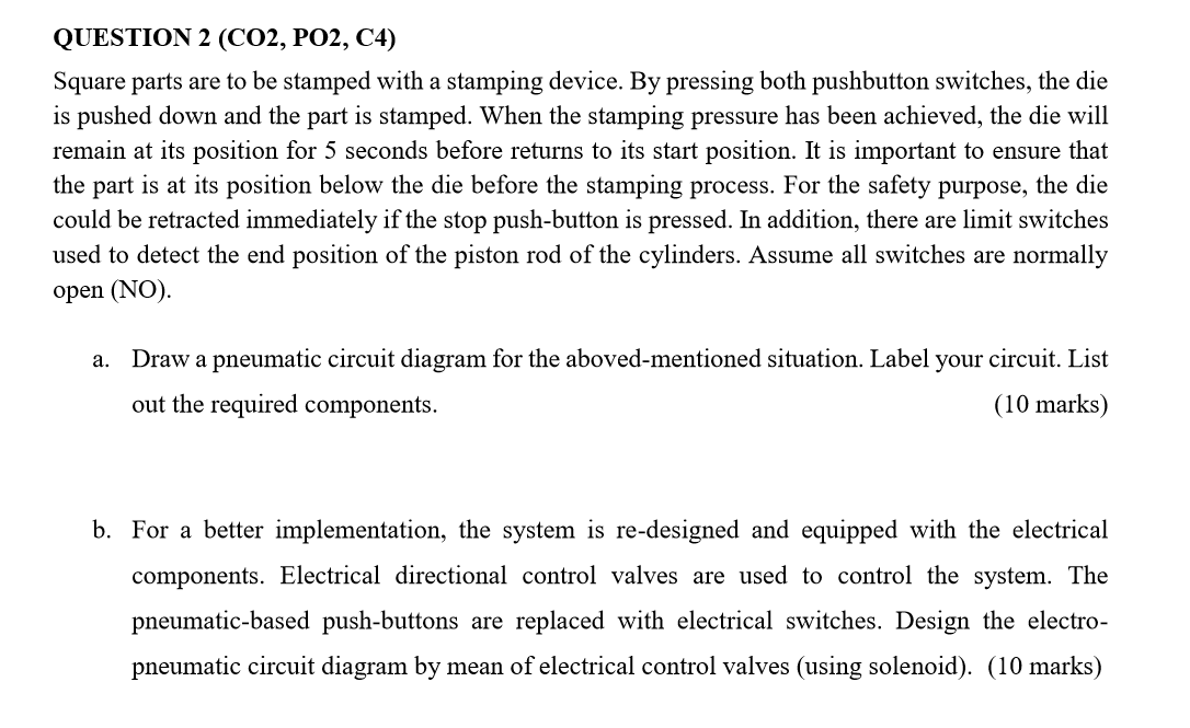
QUESTION 2 (CO2, PO2, C4) Square parts are to be stamped with a stamping device. By pressing both pushbutton switches, the die is pushed down and the part is stamped. When the stamping pressure has been achieved, the die will remain at its position for 5 seconds before returns to its start position. It is important to ensure that the part is at its position below the die before the stamping process. For the safety purpose, the die could be retracted immediately if the stop push-button is pressed. In addition, there are limit switches used to detect the end position of the piston rod of the cylinders. Assume all switches are normally open (NO) a. Draw a pneumatic circuit diagram for the aboved-mentioned situation. Label your circuit. List out the required components. (10 marks) b. For a better implementation, the system is re-designed and equipped with the electrical components. Electrical directional control valves are used to control the system. The pneumatic-based push-buttons are replaced with electrical switches. Design the electro- pneumatic circuit diagram by mean of electrical control valves (using solenoid). (10 marks) QUESTION 2 (CO2, PO2, C4) Square parts are to be stamped with a stamping device. By pressing both pushbutton switches, the die is pushed down and the part is stamped. When the stamping pressure has been achieved, the die will remain at its position for 5 seconds before returns to its start position. It is important to ensure that the part is at its position below the die before the stamping process. For the safety purpose, the die could be retracted immediately if the stop push-button is pressed. In addition, there are limit switches used to detect the end position of the piston rod of the cylinders. Assume all switches are normally open (NO) a. Draw a pneumatic circuit diagram for the aboved-mentioned situation. Label your circuit. List out the required components. (10 marks) b. For a better implementation, the system is re-designed and equipped with the electrical components. Electrical directional control valves are used to control the system. The pneumatic-based push-buttons are replaced with electrical switches. Design the electro- pneumatic circuit diagram by mean of electrical control valves (using solenoid). (10 marks)
 please solve it step by step and use clear hand writing


