Answered step by step
Verified Expert Solution
Question
1 Approved Answer
Please solve ONLY part 4 of this. UNIT 4 ANSWER NEEDED. Try to provide the diagram in circuit form for 4 bits. The details of
Please solve ONLY part 4 of this. UNIT 4 ANSWER NEEDED.
Try to provide the diagram in circuit form for 4 bits.
The details of each control signal (Unit) are as follows. Unit 1 (A/S) - Design a 4-bit adder/subtractor that accepts two 4-bits numbers, A and B, and either add them up (A + B) or subtract them (A B) depending on a control signal A/S (when the control signal is o perform ADD, otherwise if the signal is 1 then perform SUB). The result will be stored in C. Unit 2 (A/O) - Design a 4-bit AND/OR unit that accepts two 4-bits numbers, A and B, and either AND them or OR them depending on a control signal A/O (when the control signal is o perform AND, otherwise if the signal is 1 then perform OR bitwise logical operation). The result will be stored in C. Unit 3 (A/L) - Design a 4-bit ALU using Unit 1 and Unit 2. The control signal A/L will indicate which operation the ALU will perform (when the control signal is O perform Arithmetic, otherwise if the signal is 1 then perform Logic). Unit 4 (R/W)- Design three 4-bit parallel registers to hold A, B, and C where C keeps the output of the ALU. The registers have a R/W control signal that indicates that they are being written to or read from. The details of each control signal (Unit) are as follows. Unit 1 (A/S) - Design a 4-bit adder/subtractor that accepts two 4-bits numbers, A and B, and either add them up (A + B) or subtract them (A B) depending on a control signal A/S (when the control signal is o perform ADD, otherwise if the signal is 1 then perform SUB). The result will be stored in C. Unit 2 (A/O) - Design a 4-bit AND/OR unit that accepts two 4-bits numbers, A and B, and either AND them or OR them depending on a control signal A/O (when the control signal is o perform AND, otherwise if the signal is 1 then perform OR bitwise logical operation). The result will be stored in C. Unit 3 (A/L) - Design a 4-bit ALU using Unit 1 and Unit 2. The control signal A/L will indicate which operation the ALU will perform (when the control signal is O perform Arithmetic, otherwise if the signal is 1 then perform Logic). Unit 4 (R/W)- Design three 4-bit parallel registers to hold A, B, and C where C keeps the output of the ALU. The registers have a R/W control signal that indicates that they are being written to or read from
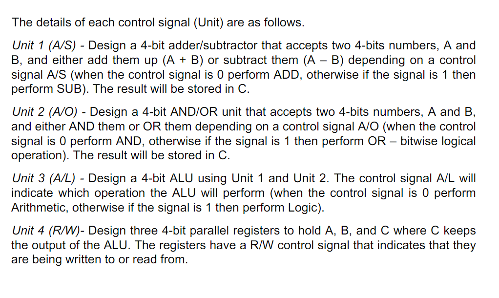
Step by Step Solution
There are 3 Steps involved in it
Step: 1
Get Instant Access to Expert-Tailored Solutions
See step-by-step solutions with expert insights and AI powered tools for academic success
Step: 2
Step: 3
Ace Your Homework with AI
Get the answers you need in no time with our AI-driven, step-by-step assistance
Get Started