

Answered step by step
Verified Expert Solution
Question
1 Approved Answer
Please upload a picture with details how this should be built or work on a breadboard. (LAB) ETE 230L To design and implement bit parallel
Please upload a picture with details how this should be built or work on a breadboard. (LAB) 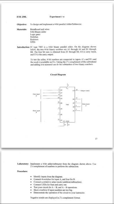
ETE 230L To design and implement bit parallel Addictsubtractor. Bread board and wires Material: 4bit Binary adder Logic gates Introduction: IC type 7483 is a 4bit binary parallel adder. Oe the diagram shown below, the two 4bit binary numbers are AI through AS and Bl through B4. The four bit sum is obtained from S1 through S4,CO is camy input, and CA is the camy output. To test the adder, 4bit numbers are coanected to inputs A's and B's and the result is available on s's Taking the 2'scomplement of the subtrahend and adding it to minuend can da the subtraction of two binary nurmben. Circuit Diagram 17 Laboratory: Implement a bit addersubomactor from the diagram showm above. Uwe complement of numbers to perfom the subtraction. Procedure: Identify inputs from the diagram. Connect 4 switches for input A, and four for B Connect a switch to select mode (additionsubtraction) Connect LEDs for Sum and carryout. Test your circuit for A B, and A-B Show overflow if input numbers are too big. Demonstrate the operation of the circuito your instructor. Negative results are displayed in 2's complement forma. ETE 230L To design and implement bit parallel Addictsubtractor. Bread board and wires Material: 4bit Binary adder Logic gates Introduction: IC type 7483 is a 4bit binary parallel adder. Oe the diagram shown below, the two 4bit binary numbers are AI through AS and Bl through B4. The four bit sum is obtained from S1 through S4,CO is camy input, and CA is the camy output. To test the adder, 4bit numbers are coanected to inputs A's and B's and the result is available on s's Taking the 2'scomplement of the subtrahend and adding it to minuend can da the subtraction of two binary nurmben. Circuit Diagram 17 Laboratory: Implement a bit addersubomactor from the diagram showm above. Uwe complement of numbers to perfom the subtraction. Procedure: Identify inputs from the diagram. Connect 4 switches for input A, and four for B Connect a switch to select mode (additionsubtraction) Connect LEDs for Sum and carryout. Test your circuit for A B, and A-B Show overflow if input numbers are too big. Demonstrate the operation of the circuito your instructor. Negative results are displayed in 2's complement forma Step by Step Solution
There are 3 Steps involved in it
Step: 1

Get Instant Access to Expert-Tailored Solutions
See step-by-step solutions with expert insights and AI powered tools for academic success
Step: 2

Step: 3
Ace Your Homework with AI
Get the answers you need in no time with our AI-driven, step-by-step assistance
Get Started
Data Management Databases And Organizations
Authors: Richard T. Watson
6th Edition
1943153035, 978-1943153039