

Question: please use C for coding Part 3: Interpreting Schematics Refer to your code in blinkLED.c How It Works First, the code sets up the microcontroller

please use C for coding
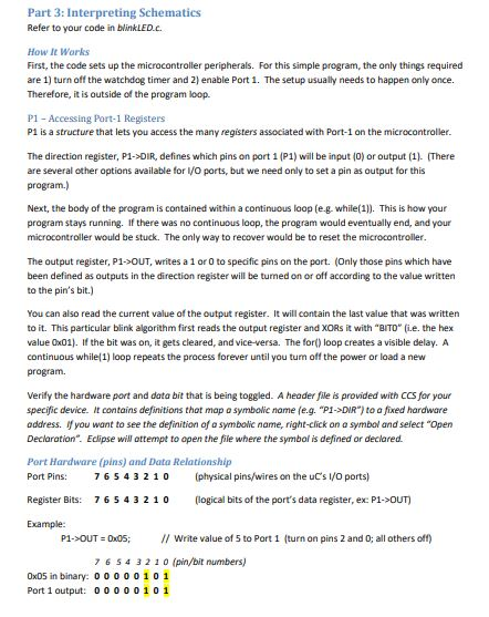
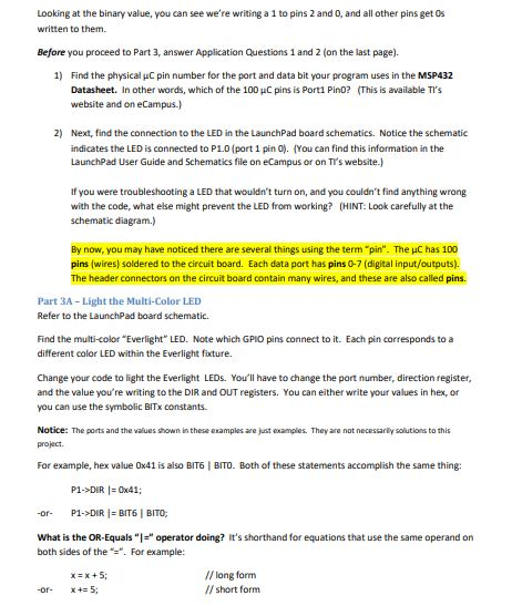
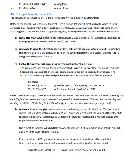
Part 3: Interpreting Schematics Refer to your code in blinkLED.c How It Works First, the code sets up the microcontroller peripherals. For this simple program, the only things required are 1) turn off the watchdog timer and 2) enable Port 1. The setup usually needs to happen only once. Therefore, it is outside of the program loop. P1 - Accessing Port-1 Registers P1 is a structure that lets you access the many registers associated with Port-1 on the microcontroller. The direction register, P1->DIR, defines which pins on port 1 (P1) will be input (0) or output (1. (There are several other options available for /O ports, but we need only to set a pin as output for this Next, the body of the program is contained within a continuous laop (e.g. whie(1). This is how your program stays running. If there was no continuous loop, the program would eventually end, and your microcontroller would be stuck. The only way to recover would be to reset the microcontroiller The output register, P1->OUT, writes a 1 or 0 to specific pins on the port. (Only those pins which have been defined as outputs in the direction register will be turned on or off according to the value written to the pin's bit.) You can also read the current value of the output register. It will contain the last value that was written to it. This particular blink algorithm first reads the output register and XORs it with "BITD" (ie. the hex value Ox01 the bit was on, it gets cleared, and vice-versa. The for) loop creates a visible delay. A continuous while(1) loop repeats the pracess forever until you tum off the power or load a new proram. Verify the hardware port and data bit that is being toggled. A header file is provided with CCS for your specific device. It contains definitions that map a symbolic name (e.g. "P1-DIRto a fixed hardware address. f you want to see the definition of a symbolic name, right-click on a symbol and select "Open Declaration. Eclipse will attempt to open the fle where the symbol is defined or declared. Port Hardware (pins) and Data Relationship Port Pins: 76543 210 (physical pins/wires on th uC's I/O ports) Register Bits: 76 543 2 10 logical bits of the port's data register, ex: P1->OUT) Example: P1-OUT Dx05 / Write value of 5 to Port 1 (turn on pins 2 and 0; all others oft) 7 6 5 4 3 2 1 0 (pin/bit numbers) 0x05 in binary: 00 00010 1 Port 1 output: 0 0 0 00101 Looking at the binary value, you can see we're writing a 1 to pins 2 and 0, and all other pins get Os written to them. Before you proceed to Part 3, answer Application Questions 1 and 2 (on the last page). 1) Find the physical uC pin number for the port and data bit your program uses in the MSP432 Datasheet. In other words, which of the 100 uC pins is Port1 Pin0? This is available TI's website and on eCampus.) 2) Next, find the connection to the LED in the LaunchPad board schematics. Notice the schematic indicates the LED is connected to P1.0 (port 1 pin O). (You can find this information in the Launchpad User Guide and Schematics file on eCampus or on website.) If you were troubleshooting a LED that wouldn't turn on, and you couldn't find anything wrong with the code, what else might prevent the LED from working? (HINT: Look carefully at the schematic diagram.) By now, you may have noticed there are several things using the term "pin". The C has 100 pins (wires) soldered to the circuit board. Each data port has pins 0-7 (digital input/outputs). The header connectors an the circuit board contain many wires, and these are also called pins. Part 3A-Light the Multi-Color LED Refer to the LaunchPad board schematic. Find the multi-color "Everlight LED. Note which GPIO pins connect to it. Each pin corresponds to a different color LED within the Everlight fixture. Change your code to light the Everlight LEDs. You'll have to change the port number, direction register and the value you're writing to the DIR and OUT registers. You can either write your values in hex, or you can use the symbolic BITx constants Notice: The ports and the values shown in these examples are just examples. They are not necessarily solutions to this project For example, hex value 0x41 is also BIT6 BITO. Both of these statements accomplish the same thing P1->DIR I-x41 What is the OR-Equals "operator doing? It's shorthand for equations that use the same operand on both sides of the. For example: l/ long form Il/ short form -or- x+= 5; P1->DIR P1->DIR 0x41 /long form Il/ short form o P1->DIR Ox41 3B-Get Input From the LaunchPad You've written data OUT to an /O port. Next, you will read data IN to an I/O port. Refer to the LaunchPad schematic (page 2). Find a button (of your choice) and note which I/O it is connected to. Reading from a port is not as straightforward as writing to it. You write using the Px- OUT register. The MSP432 has a separate register, Px->IN (where x is the port number) for reading. 1 READ THE MANUAL! Refer to the MSP432 User Guide on Digital I/O, Section 12 (available orn eCampus) for information on how the VO ports work. 2) Add code to clear the direction register (Px->DIR) on the pin you want as input. Remember that setting a '1' in a bit particular position indicates that pin will be output. Clearing it to designates that pin up for input. 0 3) Enable the internal pull-up resistor on the pushbutton's input pin. The switch grounds the pin to oV when pressed. When it isn't pressed, the pin is "floating because there are no ather physical connections to the pin to stabilize the voltage. The MSP432 has internal pullup and pulildown resistors that can be used for this purpose. Example: P3->REN - BIT3/enable resistor functionality on PORT3 BIT3 P3->OUT -BITSet the resistor to "pull up" on BIT3 NOTE: Code from Steps 1-3 belongs in the I/Micracontroller and Peripherals Setup section of the code (before the permanent loop) becouse it only needs to be done once. The pushbutton reading and turning on off the LEDs belong inside the whilef1) loop because it needs to happen repeotedly. 4) Add code to read the pin. Notice you can't read from just one pin at a time. The port input registers (such as P2->IN) are a full eight bits. Since you don't want the values of the other bits to affect the reading, you'll have to use Boolean logic operatoris) and a mask to isolate the single bit you want to evaluate. Use a mask to indicate which bit(s) you want to include. A 1 in a bit position selects that bit, and a "D ignores, or "masks" the bit Example Check BIT3, ignore all athers, write the result to a variable called myButton Your code is neater and more legible if you use an integer varlable to store the port data.) myButton P6->IN & BIT3; read from P6 and check the value of bit3 Find the physical C pin number for the port and data bit your program uses in the MSP432 Datasheet. In other words, which of the 100 uC pins is Porthis is available TI's website and on eCampus.) 1. If you were troubleshooting a LED that wouldn't turn on, and you couldn't find anything wrong with the code, what else might prevent the LED from working? schematic diagram.) 2. (HINT: Look carefully at the 3. What does the P1->DIR register do? 4. What is the purpose of the P1->OUT register when P1->REN is enabled on a particular pin? Write a C statement that reads from Port 6 and writes the value into an integer you've named data in. 5. 6. The port registers (such as DIR, OUT, etc.) are all 8-bit integers. When using these registers, how do you work with just one or two pins without affecting the other pins? Show an example of how you would make pin 2 of Port 9 an input without changing the direction of Port 9's other pins 7. When reading from a Digital I/O port, what value will it read on a pin that is set as an input but not connected to anything (i.e. floating)? HINT: Review the Digitol /O Section 12 of the User Guide. Part 3: Interpreting Schematics Refer to your code in blinkLED.c How It Works First, the code sets up the microcontroller peripherals. For this simple program, the only things required are 1) turn off the watchdog timer and 2) enable Port 1. The setup usually needs to happen only once. Therefore, it is outside of the program loop. P1 - Accessing Port-1 Registers P1 is a structure that lets you access the many registers associated with Port-1 on the microcontroller. The direction register, P1->DIR, defines which pins on port 1 (P1) will be input (0) or output (1. (There are several other options available for /O ports, but we need only to set a pin as output for this Next, the body of the program is contained within a continuous laop (e.g. whie(1). This is how your program stays running. If there was no continuous loop, the program would eventually end, and your microcontroller would be stuck. The only way to recover would be to reset the microcontroiller The output register, P1->OUT, writes a 1 or 0 to specific pins on the port. (Only those pins which have been defined as outputs in the direction register will be turned on or off according to the value written to the pin's bit.) You can also read the current value of the output register. It will contain the last value that was written to it. This particular blink algorithm first reads the output register and XORs it with "BITD" (ie. the hex value Ox01 the bit was on, it gets cleared, and vice-versa. The for) loop creates a visible delay. A continuous while(1) loop repeats the pracess forever until you tum off the power or load a new proram. Verify the hardware port and data bit that is being toggled. A header file is provided with CCS for your specific device. It contains definitions that map a symbolic name (e.g. "P1-DIRto a fixed hardware address. f you want to see the definition of a symbolic name, right-click on a symbol and select "Open Declaration. Eclipse will attempt to open the fle where the symbol is defined or declared. Port Hardware (pins) and Data Relationship Port Pins: 76543 210 (physical pins/wires on th uC's I/O ports) Register Bits: 76 543 2 10 logical bits of the port's data register, ex: P1->OUT) Example: P1-OUT Dx05 / Write value of 5 to Port 1 (turn on pins 2 and 0; all others oft) 7 6 5 4 3 2 1 0 (pin/bit numbers) 0x05 in binary: 00 00010 1 Port 1 output: 0 0 0 00101 Looking at the binary value, you can see we're writing a 1 to pins 2 and 0, and all other pins get Os written to them. Before you proceed to Part 3, answer Application Questions 1 and 2 (on the last page). 1) Find the physical uC pin number for the port and data bit your program uses in the MSP432 Datasheet. In other words, which of the 100 uC pins is Port1 Pin0? This is available TI's website and on eCampus.) 2) Next, find the connection to the LED in the LaunchPad board schematics. Notice the schematic indicates the LED is connected to P1.0 (port 1 pin O). (You can find this information in the Launchpad User Guide and Schematics file on eCampus or on website.) If you were troubleshooting a LED that wouldn't turn on, and you couldn't find anything wrong with the code, what else might prevent the LED from working? (HINT: Look carefully at the schematic diagram.) By now, you may have noticed there are several things using the term "pin". The C has 100 pins (wires) soldered to the circuit board. Each data port has pins 0-7 (digital input/outputs). The header connectors an the circuit board contain many wires, and these are also called pins. Part 3A-Light the Multi-Color LED Refer to the LaunchPad board schematic. Find the multi-color "Everlight LED. Note which GPIO pins connect to it. Each pin corresponds to a different color LED within the Everlight fixture. Change your code to light the Everlight LEDs. You'll have to change the port number, direction register and the value you're writing to the DIR and OUT registers. You can either write your values in hex, or you can use the symbolic BITx constants Notice: The ports and the values shown in these examples are just examples. They are not necessarily solutions to this project For example, hex value 0x41 is also BIT6 BITO. Both of these statements accomplish the same thing P1->DIR I-x41 What is the OR-Equals "operator doing? It's shorthand for equations that use the same operand on both sides of the. For example: l/ long form Il/ short form -or- x+= 5; P1->DIR P1->DIR 0x41 /long form Il/ short form o P1->DIR Ox41 3B-Get Input From the LaunchPad You've written data OUT to an /O port. Next, you will read data IN to an I/O port. Refer to the LaunchPad schematic (page 2). Find a button (of your choice) and note which I/O it is connected to. Reading from a port is not as straightforward as writing to it. You write using the Px- OUT register. The MSP432 has a separate register, Px->IN (where x is the port number) for reading. 1 READ THE MANUAL! Refer to the MSP432 User Guide on Digital I/O, Section 12 (available orn eCampus) for information on how the VO ports work. 2) Add code to clear the direction register (Px->DIR) on the pin you want as input. Remember that setting a '1' in a bit particular position indicates that pin will be output. Clearing it to designates that pin up for input. 0 3) Enable the internal pull-up resistor on the pushbutton's input pin. The switch grounds the pin to oV when pressed. When it isn't pressed, the pin is "floating because there are no ather physical connections to the pin to stabilize the voltage. The MSP432 has internal pullup and pulildown resistors that can be used for this purpose. Example: P3->REN - BIT3/enable resistor functionality on PORT3 BIT3 P3->OUT -BITSet the resistor to "pull up" on BIT3 NOTE: Code from Steps 1-3 belongs in the I/Micracontroller and Peripherals Setup section of the code (before the permanent loop) becouse it only needs to be done once. The pushbutton reading and turning on off the LEDs belong inside the whilef1) loop because it needs to happen repeotedly. 4) Add code to read the pin. Notice you can't read from just one pin at a time. The port input registers (such as P2->IN) are a full eight bits. Since you don't want the values of the other bits to affect the reading, you'll have to use Boolean logic operatoris) and a mask to isolate the single bit you want to evaluate. Use a mask to indicate which bit(s) you want to include. A 1 in a bit position selects that bit, and a "D ignores, or "masks" the bit Example Check BIT3, ignore all athers, write the result to a variable called myButton Your code is neater and more legible if you use an integer varlable to store the port data.) myButton P6->IN & BIT3; read from P6 and check the value of bit3 Find the physical C pin number for the port and data bit your program uses in the MSP432 Datasheet. In other words, which of the 100 uC pins is Porthis is available TI's website and on eCampus.) 1. If you were troubleshooting a LED that wouldn't turn on, and you couldn't find anything wrong with the code, what else might prevent the LED from working? schematic diagram.) 2. (HINT: Look carefully at the 3. What does the P1->DIR register do? 4. What is the purpose of the P1->OUT register when P1->REN is enabled on a particular pin? Write a C statement that reads from Port 6 and writes the value into an integer you've named data in. 5. 6. The port registers (such as DIR, OUT, etc.) are all 8-bit integers. When using these registers, how do you work with just one or two pins without affecting the other pins? Show an example of how you would make pin 2 of Port 9 an input without changing the direction of Port 9's other pins 7. When reading from a Digital I/O port, what value will it read on a pin that is set as an input but not connected to anything (i.e. floating)? HINT: Review the Digitol /O Section 12 of the User Guide
Step by Step Solution
There are 3 Steps involved in it

Get step-by-step solutions from verified subject matter experts