Answered step by step
Verified Expert Solution
Link Copied!

Question

1 Approved Answer

Please use C-PROGRAMMING. please modify tutorial code to work with question 1. Board is TM4C123G LaunchPad. Question 1: Write a program that simulates a pedestrian

Please use C-PROGRAMMING. please modify tutorial code to work with question 1. Board is TM4C123G LaunchPad.

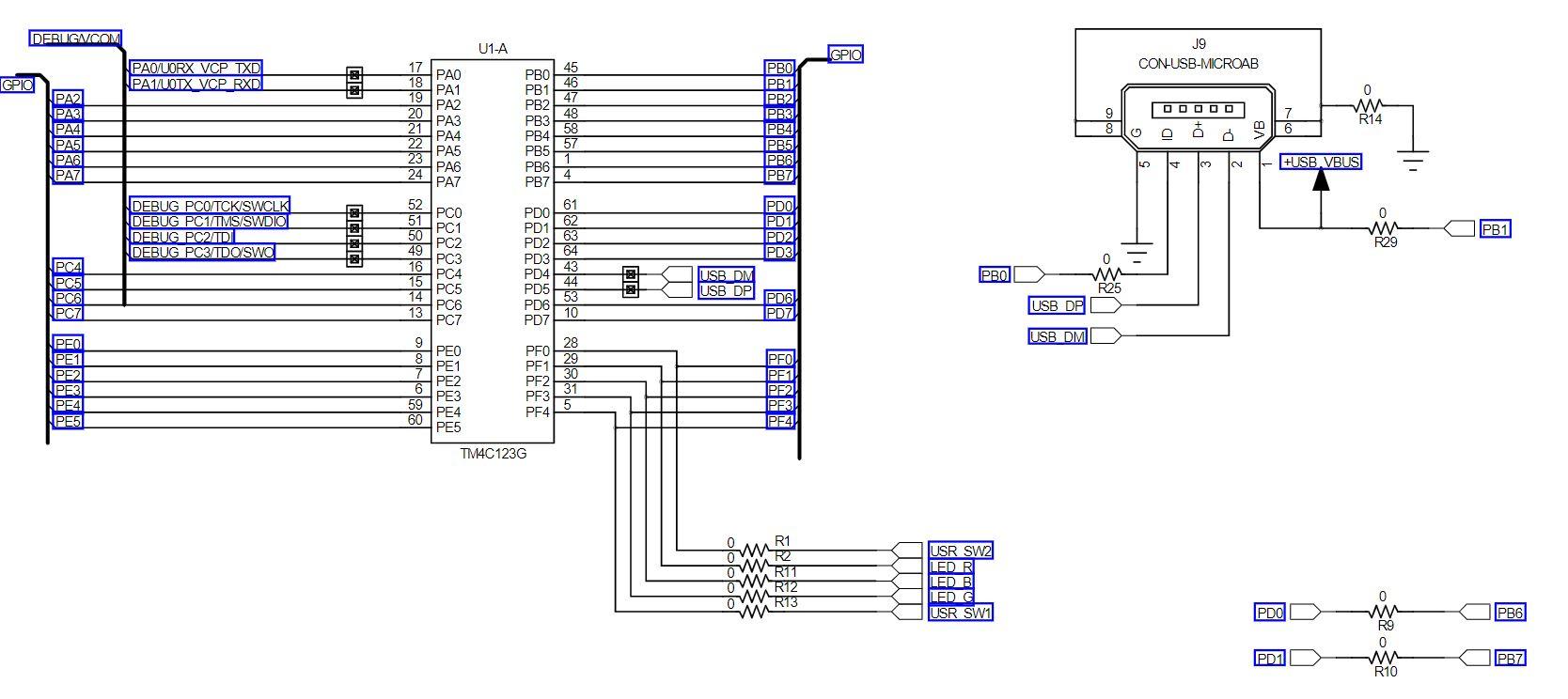
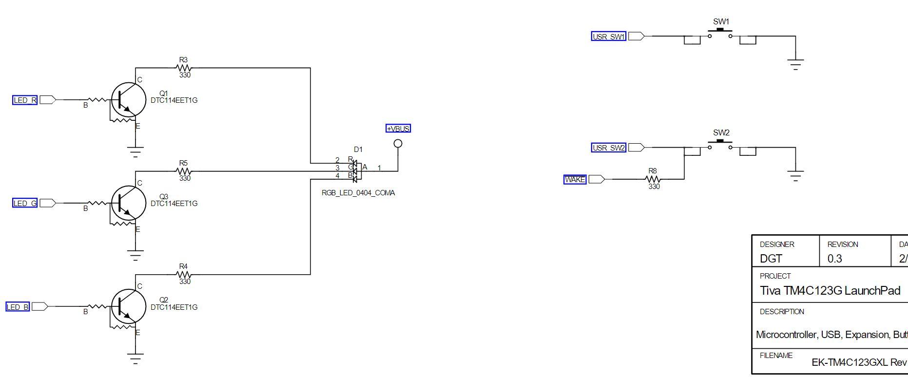
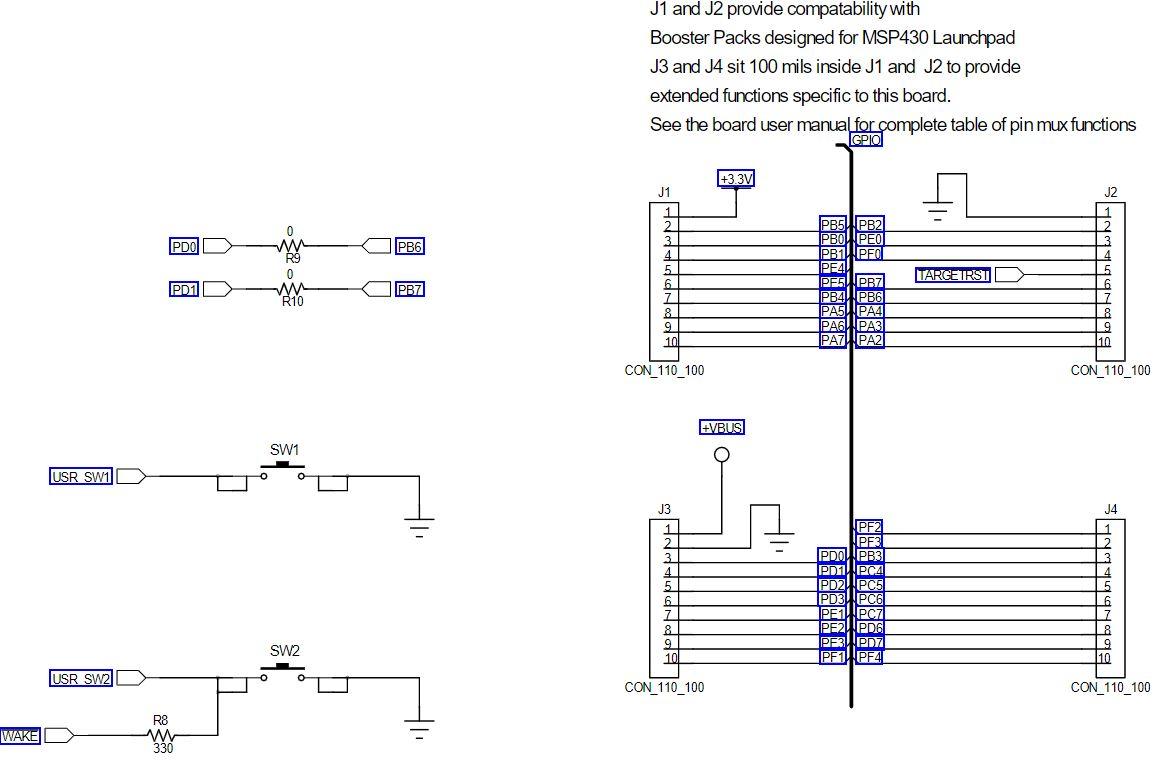
Question 1: Write a program that simulates a pedestrian controlled traffic light. The light flashes green with an interval of a half second. If the SW1 button is pressed, the light changes to yellow for 1 second, then turns solid red for 5 seconds. After the 5 seconds, the light returns to the default state of flashing green. Note that if you quickly press the button while the LED is flashing green it may not detect the button press and activate the signal. Why do you think that is? What is the minimum length of time you must hold the button down to guarantee that the button press is detected?

Note that SW1 will work as expected, however, bit 0 of Port F is locked and you will need to add the following two lines of code before you initialize the Port F registers for SW2: GPIO_PORTF_LOCK_R = GPIO_LOCK_KEY; GPIO_PORTF_CR_R |= SW2;

Please modify the code below to work with question 1

#include "tm4c123gh6pm.h" // device specific include file

#define YELLOW 0XA //BIT 2 or 0x5 is blue, BIT1 or 0x3 is red, BIT3 or 0x8 is green, yellow is 0xA #define RED 0x3 #define GREEN 0x8 #define WHITE 0xE #define DELAY_LOOPS 2000000 #define BRIEF_PAUSE 500000

int main(void) { int loopCount; // counter to generate delay

volatile int temp; // temporary variable to force peripheral bus read

// activate clock for GPIO Port F SYSCTL_RCGC2_R |= SYSCTL_RCGC2_GPIOF;

// allow a few cycles for clock to start temp = SYSCTL_RCGC2_R;

// enable Port F Bit 2 connected to white LED as digital output. For full colour spectrum GPIO_PORTF_DIR_R |= WHITE; GPIO_PORTF_DEN_R |= WHITE;

while(1) { // generate delay GPIO_PORTF_DATA_R ^= GREEN; // toggle ON GREEN LED for(loopCount = 0; loopCount

image text in transcribedimage text in transcribedimage text in transcribed

DEBUGNCOM U1-A GPIO J9 CON-USB-MICROAB PAO/UORX VCP TXD PAMUOTX VCP RXD GPIC PBO! PB1 PB2 | PBS 45 PBO PB1 46 47 PB2 48 PB3 PB4 58 PB5 57 DOOOO 9 8 7 6 PA2 PA3 PA4 PA5 PA6 PAZ w R14 PB4! 20 PA4 PB5 PB6H PB6! LO - +USB.VBUS PB7 17 PAO 18 19 PA1 PA2 20 21 22 23 PA5 24 PAS PAT 52 51 PCO 50 PC1 49 PC3 16 PC4 15 PC5 14 PC6 13 PC7 DEBUG PCO/TCK/SWCLK DEBUG PC1/TMS/SWDIO DEBUG PC2UDI DEBUG PC3/TDOSWOI B PD1 62 0 w R29 PB1 20 PC2 PB7 61 PDO PD2 63 64 PD3 PD4 PD5 53 PD6 PD7 10 PDO) PD1) PD2! PD3 USB DM USB DP PD6 PD7 PC4 PC5 PC6 PCA P w R25 USB DP USB DM 9 PEO PE1 PE2 PE3 PE4 PE5 PEO PE1 PE2 PE3 PE4 PE5 PFO PF1 PF2 PF3 PF4 28 29 30 31 5 PFO! PF1 PF2 PF3 PE4 59 60 TM4C123G w w R11 USR SW2 LED R LED B LED C USR SW1 R12 W R13 PDO 0 w R9 0 PB6 nn PD1 PB7 R10 SW1 USR SW1 R3 330 LED R Q1 DTC114EET1G B +VBUS SW2 USR SW2 D1 2 3 . R5 w 330 1 WAKE R8 w 330 RGB_LED_0404_COMA LED G Q3 DTC114EET1G DA DESIGNER DGT REVISION 0.3 2 R4 w PROJECT Tiva TM4C123G LaunchPad LED B Q2 DTC114EET1G DESCRIPTION Microcontroller, USB, Expansion, Buti FILENAME EK-TM4C123GXL Rev J1 and J2 provide compatability with Booster Packs designed for MSP430 Launchpad J3 and J4 sit 100 mils inside J1 and J2 to provide extended functions specific to this board. See the board user manual for complete table of pin mux functions GPIO +3.3V J2 PDO PB6 W R9 0 W- R10 J1 1 2 3 4 4 5 6 7 7 8 9 101 TARGETRST PD1 PB7 PB5PB2 PBOX PEOL PB11PFO PE PE5PB7 IPB4 IPB6 PA5U PA4 PAZ PAZ 10 CON_110_100 CON_110_100 VBUS SW1 USR SW1 J3 J4 = 1 1 2 3 4 5 6 7 8 PF2 PF3 PDO PB3 PDI!!PCA PD11 PD2!!PCS , PD3U!PCG PE14. PC7 PE2|PDG PEWPD7 PF1 PF4 SW2 10. 10 USR SW21 O CON_110_100 CON_110_100 R8 W 330 TH WAKE DEBUGNCOM U1-A GPIO J9 CON-USB-MICROAB PAO/UORX VCP TXD PAMUOTX VCP RXD GPIC PBO! PB1 PB2 | PBS 45 PBO PB1 46 47 PB2 48 PB3 PB4 58 PB5 57 DOOOO 9 8 7 6 PA2 PA3 PA4 PA5 PA6 PAZ w R14 PB4! 20 PA4 PB5 PB6H PB6! LO - +USB.VBUS PB7 17 PAO 18 19 PA1 PA2 20 21 22 23 PA5 24 PAS PAT 52 51 PCO 50 PC1 49 PC3 16 PC4 15 PC5 14 PC6 13 PC7 DEBUG PCO/TCK/SWCLK DEBUG PC1/TMS/SWDIO DEBUG PC2UDI DEBUG PC3/TDOSWOI B PD1 62 0 w R29 PB1 20 PC2 PB7 61 PDO PD2 63 64 PD3 PD4 PD5 53 PD6 PD7 10 PDO) PD1) PD2! PD3 USB DM USB DP PD6 PD7 PC4 PC5 PC6 PCA P w R25 USB DP USB DM 9 PEO PE1 PE2 PE3 PE4 PE5 PEO PE1 PE2 PE3 PE4 PE5 PFO PF1 PF2 PF3 PF4 28 29 30 31 5 PFO! PF1 PF2 PF3 PE4 59 60 TM4C123G w w R11 USR SW2 LED R LED B LED C USR SW1 R12 W R13 PDO 0 w R9 0 PB6 nn PD1 PB7 R10 SW1 USR SW1 R3 330 LED R Q1 DTC114EET1G B +VBUS SW2 USR SW2 D1 2 3 . R5 w 330 1 WAKE R8 w 330 RGB_LED_0404_COMA LED G Q3 DTC114EET1G DA DESIGNER DGT REVISION 0.3 2 R4 w PROJECT Tiva TM4C123G LaunchPad LED B Q2 DTC114EET1G DESCRIPTION Microcontroller, USB, Expansion, Buti FILENAME EK-TM4C123GXL Rev J1 and J2 provide compatability with Booster Packs designed for MSP430 Launchpad J3 and J4 sit 100 mils inside J1 and J2 to provide extended functions specific to this board. See the board user manual for complete table of pin mux functions GPIO +3.3V J2 PDO PB6 W R9 0 W- R10 J1 1 2 3 4 4 5 6 7 7 8 9 101 TARGETRST PD1 PB7 PB5PB2 PBOX PEOL PB11PFO PE PE5PB7 IPB4 IPB6 PA5U PA4 PAZ PAZ 10 CON_110_100 CON_110_100 VBUS SW1 USR SW1 J3 J4 = 1 1 2 3 4 5 6 7 8 PF2 PF3 PDO PB3 PDI!!PCA PD11 PD2!!PCS , PD3U!PCG PE14. PC7 PE2|PDG PEWPD7 PF1 PF4 SW2 10. 10 USR SW21 O CON_110_100 CON_110_100 R8 W 330 TH WAKE

Step by Step Solution

There are 3 Steps involved in it

Step: 1

blur-text-image

Get Instant Access to Expert-Tailored Solutions

See step-by-step solutions with expert insights and AI powered tools for academic success

Step: 2

blur-text-image

Step: 3

blur-text-image

Ace Your Homework with AI

Get the answers you need in no time with our AI-driven, step-by-step assistance

Get Started

Recommended Textbook for

Spomenik Monument Database

Authors: Donald Niebyl, FUEL, Damon Murray, Stephen Sorrell

1st Edition

0995745536, 978-0995745537

Students also viewed these Databases questions