

Answered step by step
Verified Expert Solution
Question
1 Approved Answer
Please use the EDAplayground to finish this program, and the code is available in this website: https://www.edaplayground.com/x/3aGb Part 1: The ALU The ALU is a

Please use the EDAplayground to finish this program, and the code is available in this website: https://www.edaplayground.com/x/3aGb
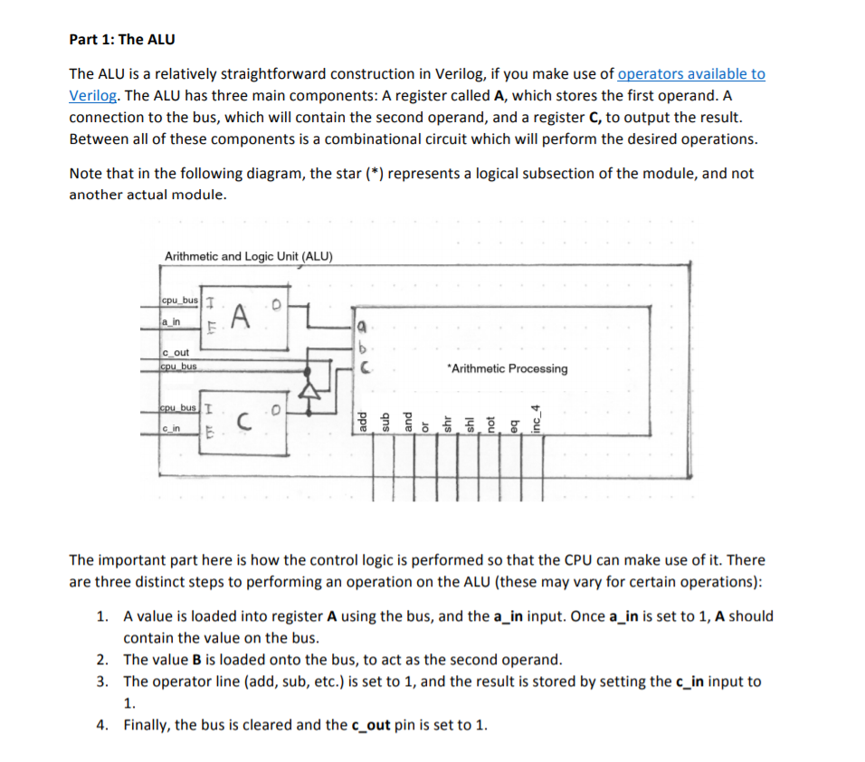
Part 1: The ALU The ALU is a relatively straightforward construction in Verilog, if you make use of operators available to Verilog. The ALU has three main components: A register called A, which stores the first operand. A connection to the bus, which will contain the second operand, and a register C, to output the result. Between all of these components is a combinational circuit which will perform the desired operations. Note that in the following diagram, the star (*) represents a logical subsection of the module, and not another actual module. Arithmetic and Logic Unit (ALU) bus c out Arithmetic Processing 0 G in The important part here is how the control logic is performed so that the CPU can make use of it. There are three distinct steps to performing an operation on the ALU (these may vary for certain operations): A value is loaded into register A using the bus, and the a_in input. Once a_in is set to 1, A should contain the value on the bus. The value B is loaded onto the bus, to act as the second operand The operator line (add, sub, etc.) is set to 1, and the result is stored by setting the c_in input to 1. 2. 3. 4. Finally, the bus is cleared and the c_out pin is set to 1. Part 1: The ALU The ALU is a relatively straightforward construction in Verilog, if you make use of operators available to Verilog. The ALU has three main components: A register called A, which stores the first operand. A connection to the bus, which will contain the second operand, and a register C, to output the result. Between all of these components is a combinational circuit which will perform the desired operations. Note that in the following diagram, the star (*) represents a logical subsection of the module, and not another actual module. Arithmetic and Logic Unit (ALU) bus c out Arithmetic Processing 0 G in The important part here is how the control logic is performed so that the CPU can make use of it. There are three distinct steps to performing an operation on the ALU (these may vary for certain operations): A value is loaded into register A using the bus, and the a_in input. Once a_in is set to 1, A should contain the value on the bus. The value B is loaded onto the bus, to act as the second operand The operator line (add, sub, etc.) is set to 1, and the result is stored by setting the c_in input to 1. 2. 3. 4. Finally, the bus is cleared and the c_out pin is set to 1Step by Step Solution
There are 3 Steps involved in it
Step: 1

Get Instant Access to Expert-Tailored Solutions
See step-by-step solutions with expert insights and AI powered tools for academic success
Step: 2

Step: 3
Ace Your Homework with AI
Get the answers you need in no time with our AI-driven, step-by-step assistance
Get Started
Systems Analysis And Synthesis Bridging Computer Science And Information Technology
Authors: Barry Dwyer
1st Edition
0128054492, 9780128054499