Question: Please use the information given to completely fill in tables 1-3 . Please also draw a vector sum diagram and a component diagram for the
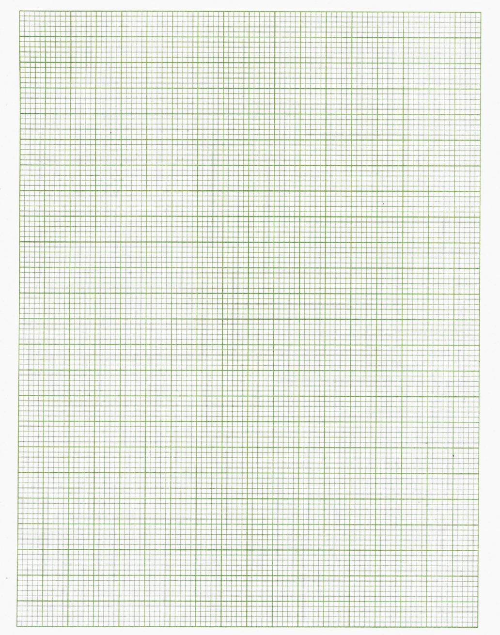
Please use the information given to completely fill in tables 1-3. Please also draw a vector sum diagram and a component diagram for the results. Please provide any explanations and show all work. Please do NOT skip anything. Thank you!

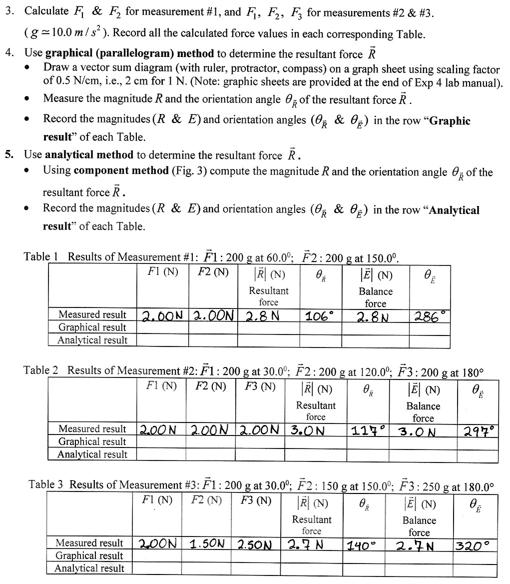
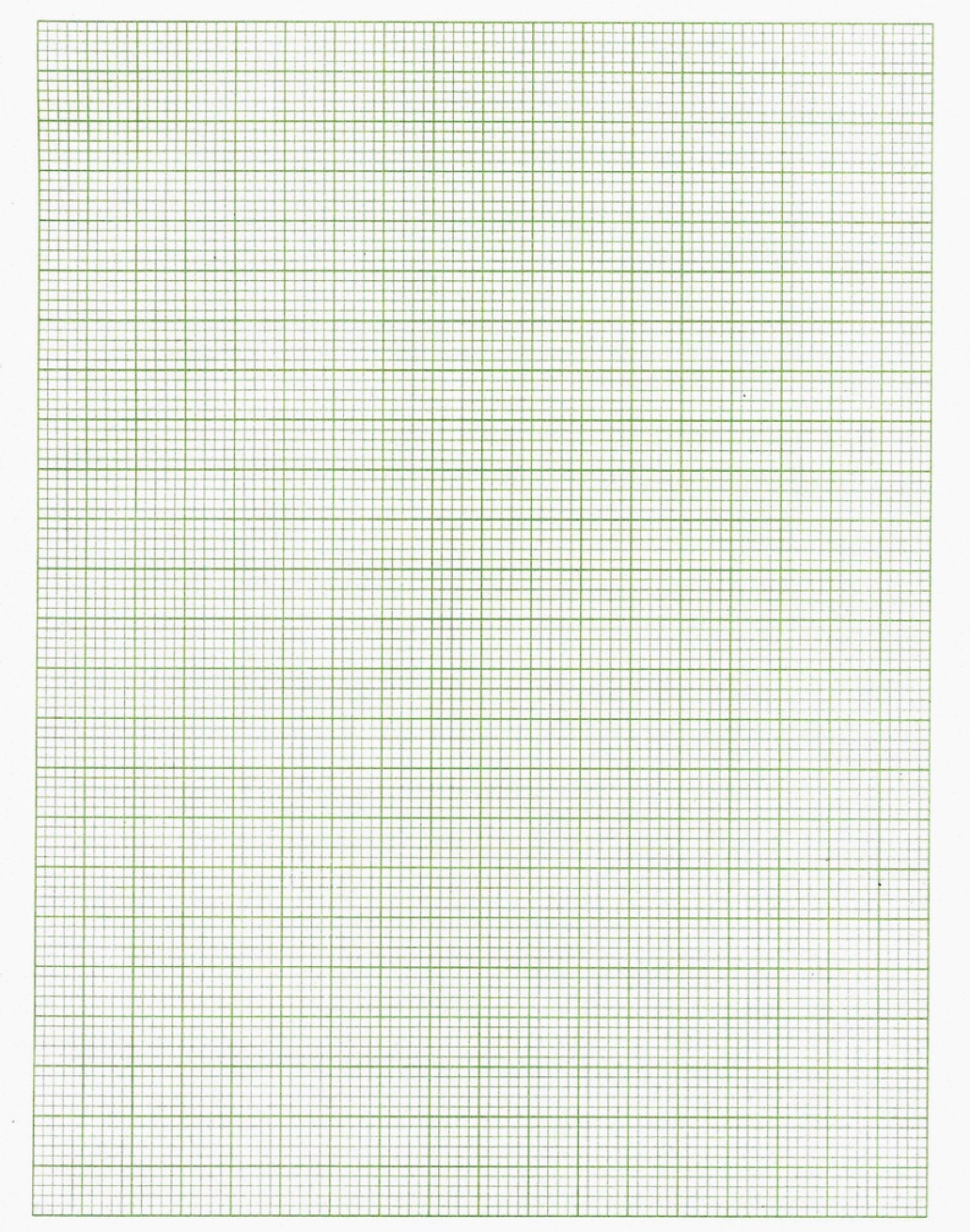
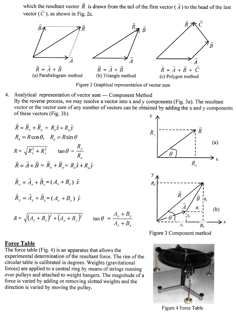
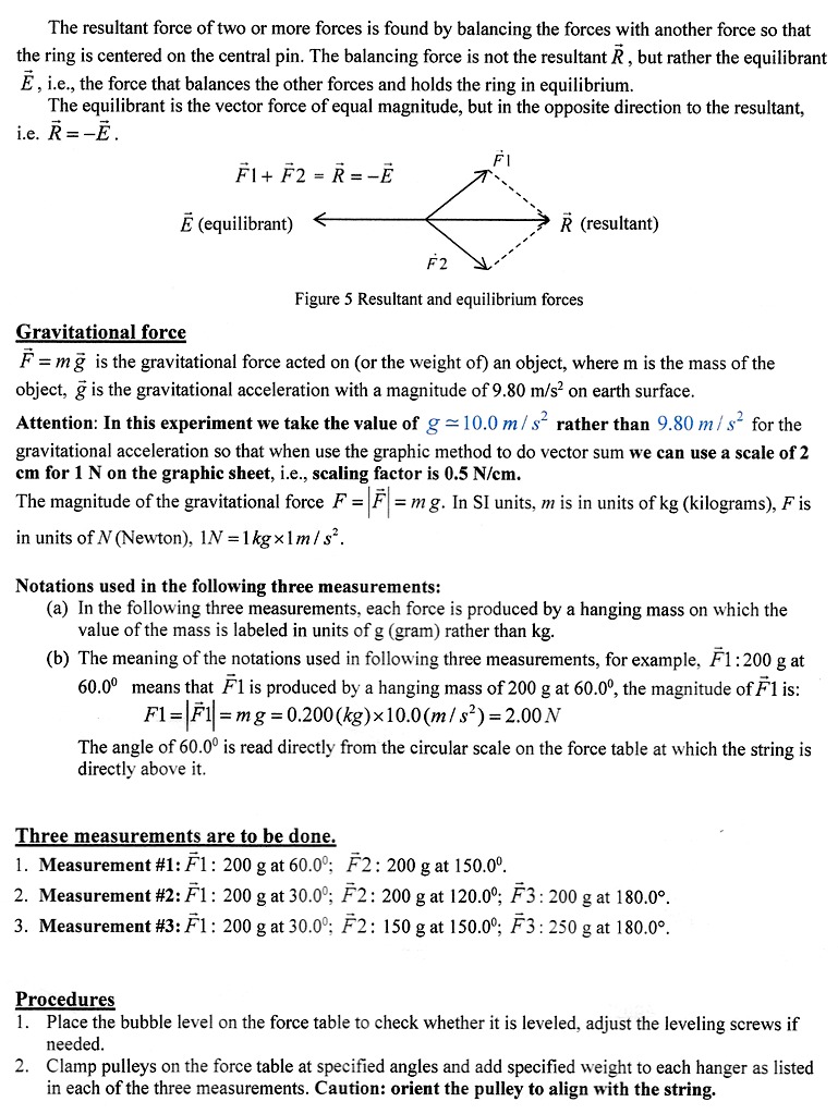
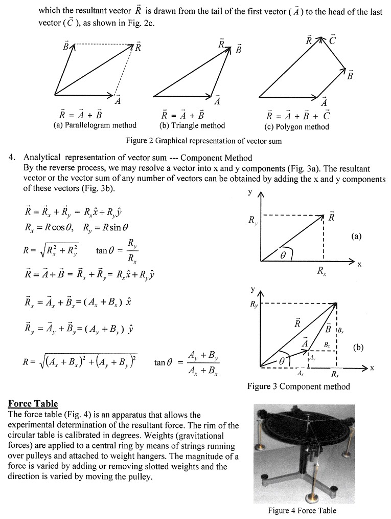
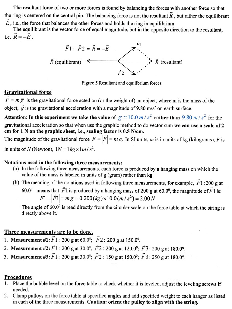
3. Graphical representation of vector sum (vector addition and subtraction) (a) Parallelogram Method Figure 2a shows the addition of two vectors, 1e A + B using parallelogram method m which A and B are the adjacent sides of the parallelogram The arrow diagonal of the parallelogram R is the resultant vector or vector sum of A + B, 1e R= A + B. (b) Triangle Method and Polygon Method An equivalent method of nding R is to add the two vectors \"head to tail\": the head of A to the tail of B , as shown in Fig. 2b. The resultant vector R is drawn from the tail of the vectorA to the head of B . If more than two vectors are added, the head to tail method forms a polygon in 3. Calculate F, & F2 for measurement #1, and FI, F2, F; for measurements #2 & #3. (g =10.0 m/ s' ). Record all the calculated force values in each corresponding Table. 4. Use graphical (parallelogram) method to determine the resultant force R Draw a vector sum diagram (with ruler, protractor, compass) on a graph sheet using scaling factor of 0.5 N/cm, i.e., 2 cm for 1 N. (Note: graphic sheets are provided at the end of Exp 4 lab manual). Measure the magnitude R and the orientation angle Op of the resultant force R Record the magnitudes (R & E) and orientation angles (OR & 0) in the row "Graphic result" of each Table. 5. Use analytical method to determine the resultant force R. Using component method (Fig. 3) compute the magnitude R and the orientation angle Op of the resultant force R . Record the magnitudes (R & E) and orientation angles (OR & OF) in the row "Analytical result" of each Table. Table 1 Results of Measurement #1: F1 : 200 g at 60.00; F2: 200 g at 150.00. F1 (N) F2 (N) R (N ) |E (N) Resultant Balance force force Measured result 12.60N 2.0ON 2.8 N 106 2.8N 286 Graphical result Analytical result Table 2 Results of Measurement #2: F1 : 200 g at 30.0; F2 : 200 g at 120.09; F3 : 200 g at 180 F1 (N) F2 (N) F3 (N) |R (N) |E| (N) Resultant Balance force force Measured result 200N 2.00N 2.00N 3.ON 1170 3.ON 2970 Graphical result Analytical result Table 3 Results of Measurement #3: F1 : 200 g at 30.00; F2: 150 g at 150.00; F3 : 250 g at 180.0 FI (N) F2 (N) F3 (N) |R (N) E (N) Resultant Balance force force Measured result 20ON 1.50N 2.5ON 2. 7 N 140 0 2. 7 N 320 Graphical result Analytical result\fwhich the resultant vector ft is drawn from the tail of the rst vector ( H )to the head of the last vector (5 }, as shown in Fig. 2c. - _ ft ' f: R : B E .3 A =+fs =1+ =i+i+ff {a} Farallelograrn method {b} Triangle method (c) Polygon method Figure 2 Graphical representation of vector sum 4. Analytical representation of vector sum .... Component Method By the reverse process, we may resolve a vector into x and y components (Fig. 3a). The resultant vector or the vector sum of any number of vectors can be obtained by adding the x and y components of these vectors (Fig. 3b}. _. R = a; +152; = always Rx =Rcos9, R1, = Reine? J\" .i' y Jr' ., A +B R=./(Ax+ax)i+iay+syi tan6= J\" J\" AI+BI Force Table The force table (Fig. 4) is an apparatus that allows the experimental determination of the resultant force. The rim of the circular table is calibrated in degrees. Weights (gravitational forces) are applied to a central ring by means of strings running over pulleys and attached to weight hangers. The magnitude of a force is varied by adding or removing slotted weights and the direction is varied by moving the pulley. Figure 4 Force Table The resultant force of two or more forces is found by balancing the forces with another fbrce so that the ring is centered on the central pin. The balancing force is not the resultant R , but rather the equilibrant E , i.e., the force that balances the other forces and holds the ring in equilibrium. The equilibrant is the vector force of equal magnitude, but in the opposite direction to the resultant, i.e. R=E. 131+ F2 = il=-E' E (equilibran E (resultant) Figure 5 Rasultant and equilibrium forces Gravitational force 13 = m g is the gravitational force acted on (or the weight of) an object, where m is the mass of the object, g is the gravitational acceleration with a magnitude of 9.8!} n'iis2 on earth surface. Attention: In this experiment we take the value of g 2 10.0 at! :32 rather than 9.8!] m I s2 for the gravitational acceleration so that when use the graphic method to do vector sum we can use a scale of 2 cm for 1 N on the graphic sheet, i.e., seating factor is 0.5 Mom. The magnitude of the gravitational force F = [F' = m g. In SI units, or is in units of kg (kilograms), F is in units ofNINewton], 1N =1tgximret. Notations used in the following three measurements: (a) In the following three measurements, each force is produced by a hanging mass on which the value of the mass is labeled in units of g (gram) rather than kg. (b) The meaning of the notations used in following titres measurements, for example, Fl :2l} g at 0.00 means that 131 is produced by a hanging mass of 21m g at dill)\
Step by Step Solution
There are 3 Steps involved in it

Get step-by-step solutions from verified subject matter experts


