please use the structure given to create the code for part 5. Here Is the current code I have. I just need to create a bitwise AND code and a bitwise OR code so that a port map can be created in the ALU. please fix the ALU code as needed so that it can run properly with the port maps.
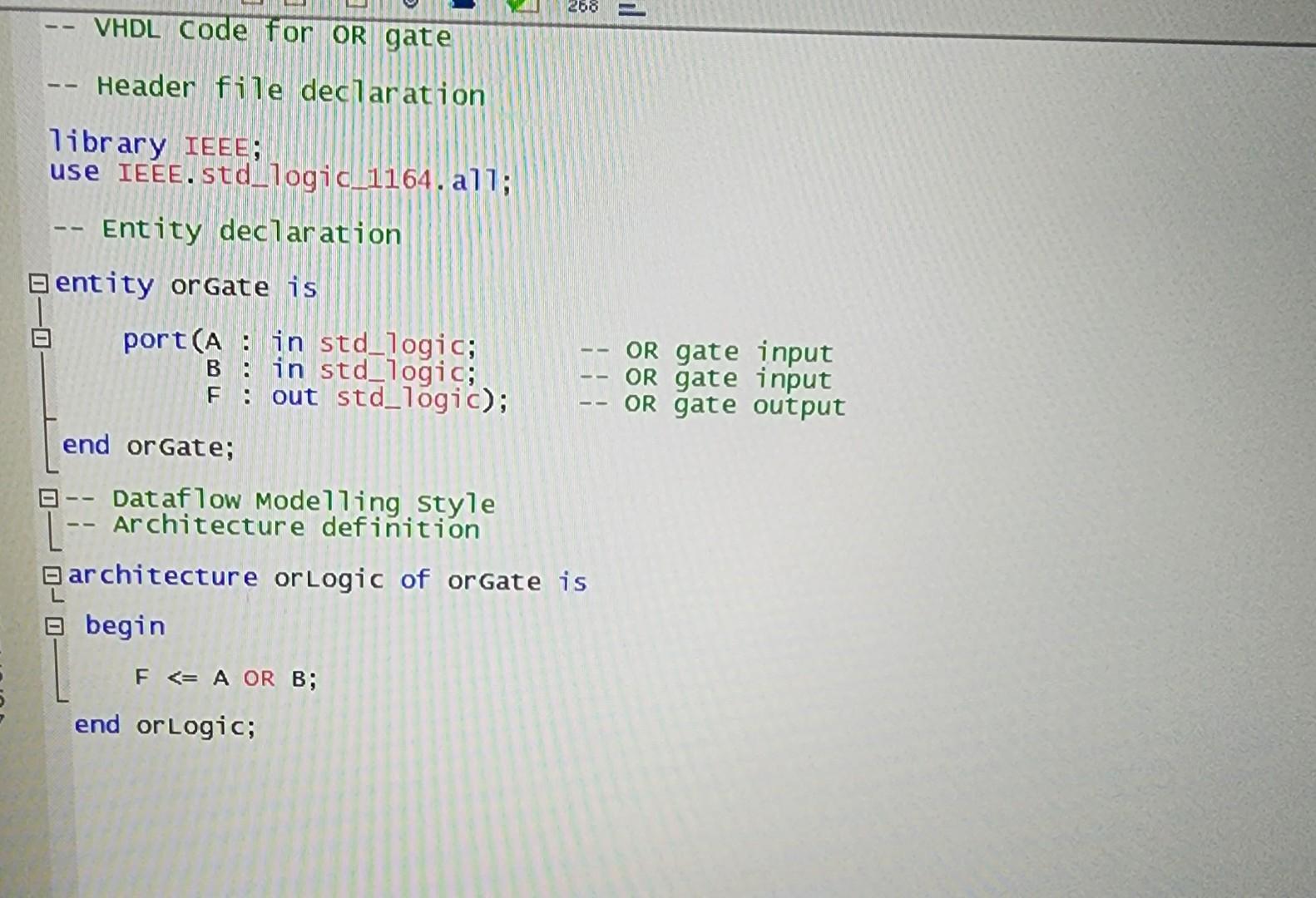
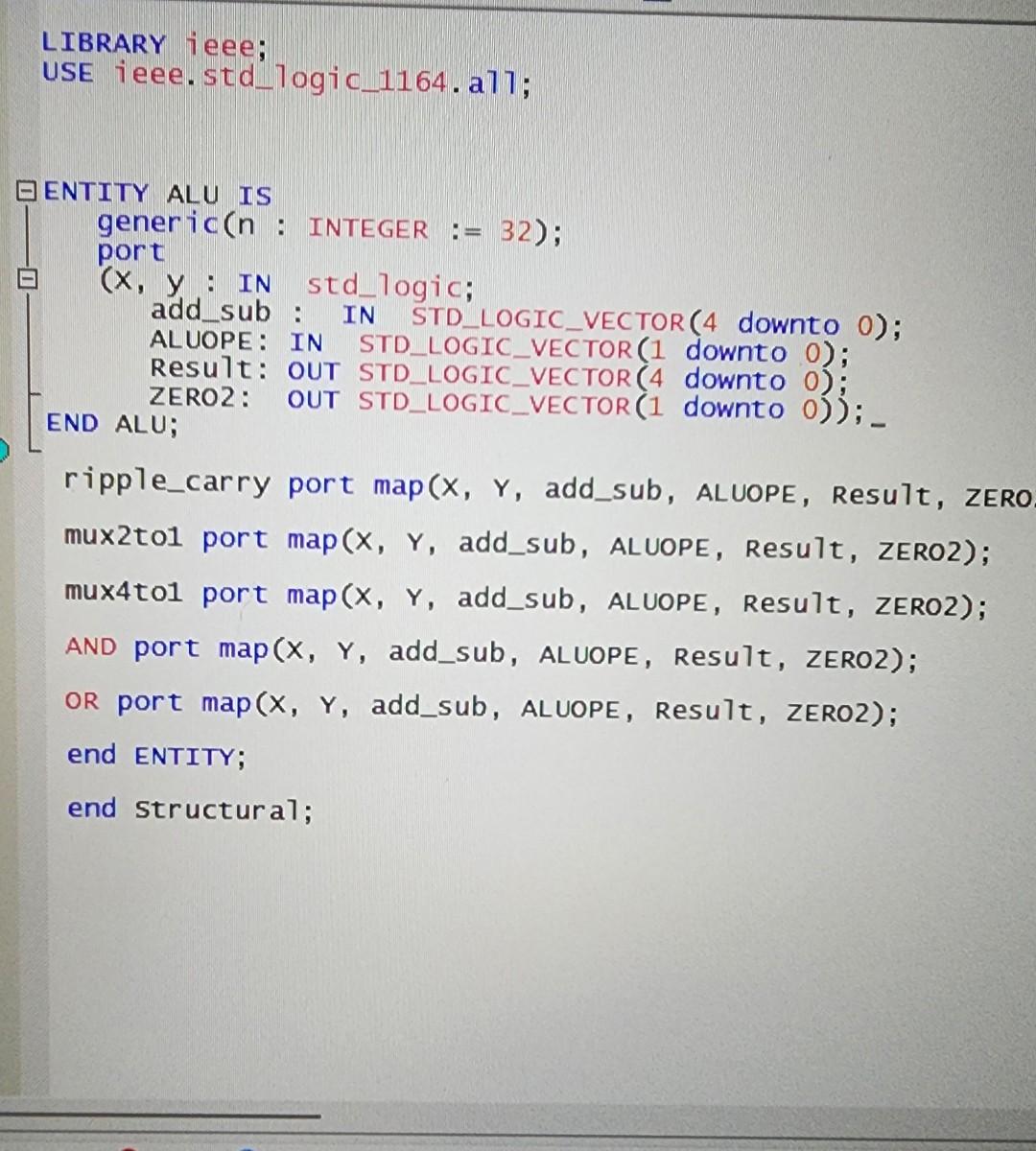
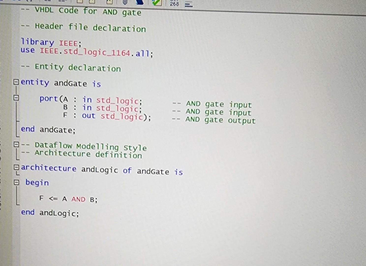
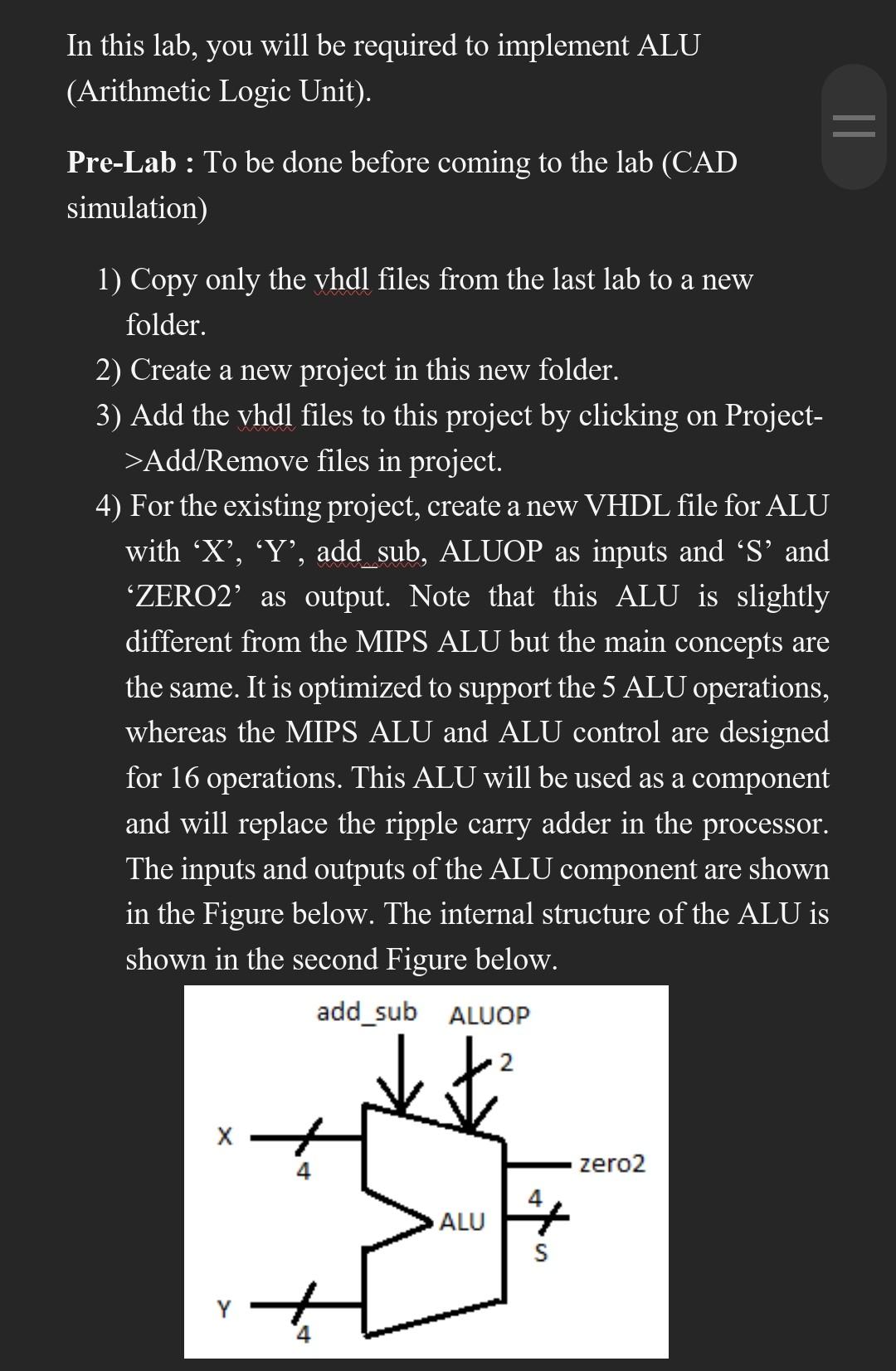
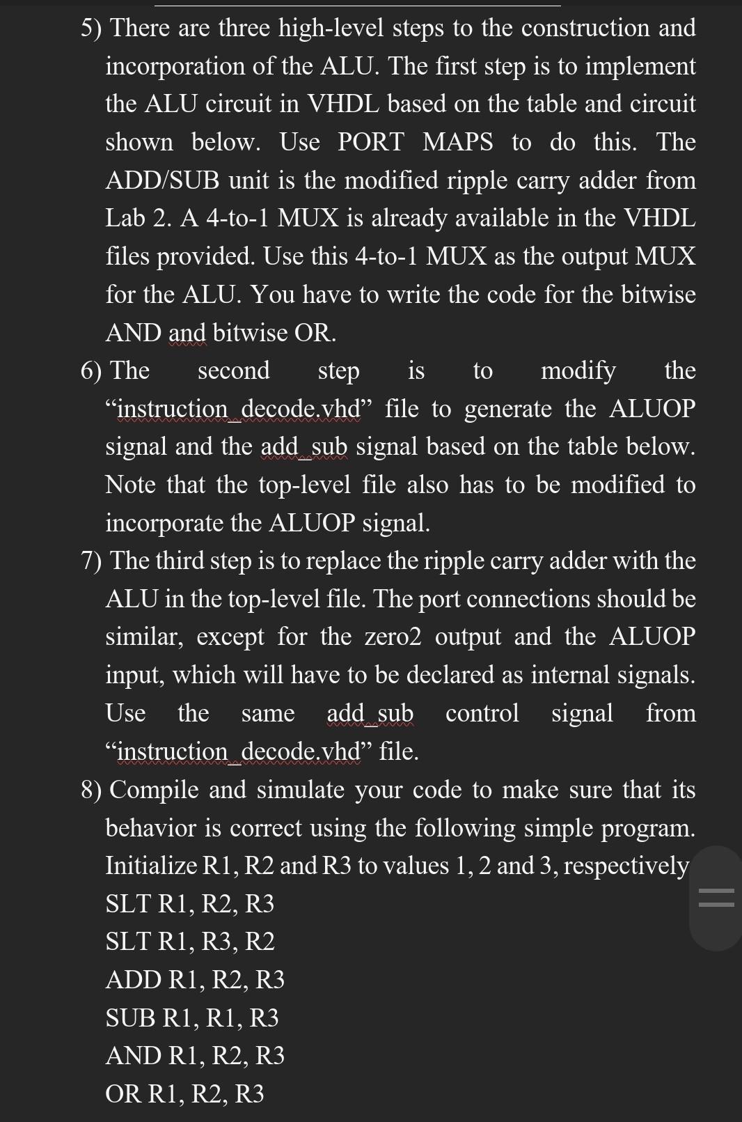
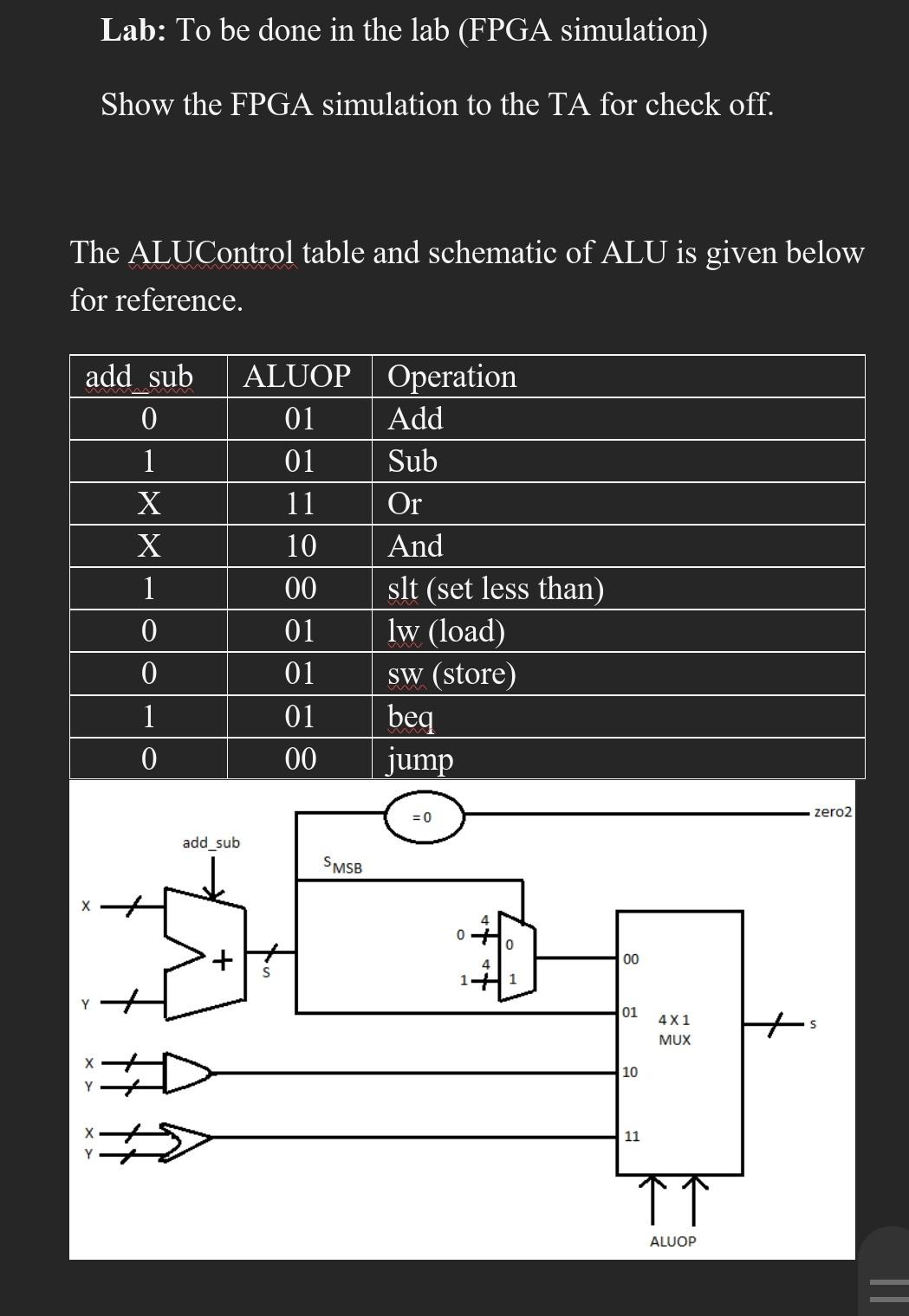
In this lab, you will be required to implement ALU (Arithmetic Logic Unit). Pre-Lab : To be done before coming to the lab (CAD simulation) 1) Copy only the vhdl files from the last lab to a new folder. 2) Create a new project in this new folder. 3) Add the vhdl files to this project by clicking on Project> Add/Remove files in project. 4) For the existing project, create a new VHDL file for ALU with ' X ', ' Y ', add sub, ALUOP as inputs and 'S' and 'ZERO2' as output. Note that this ALU is slightly different from the MIPS ALU but the main concepts are the same. It is optimized to support the 5 ALU operations, whereas the MIPS ALU and ALU control are designed for 16 operations. This ALU will be used as a component and will replace the ripple carry adder in the processor. The inputs and outputs of the ALU component are shown in the Figure below. The internal structure of the ALU is shown in the second Figure below. 5) There are three high-level steps to the construction and incorporation of the ALU. The first step is to implement the ALU circuit in VHDL based on the table and circuit shown below. Use PORT MAPS to do this. The ADD/SUB unit is the modified ripple carry adder from Lab 2. A 4-to-1 MUX is already available in the VHDL files provided. Use this 4-to-1 MUX as the output MUX for the ALU. You have to write the code for the bitwise AND and bitwise OR. 6) The second step is to modify the "instruction decode.vhd" file to generate the ALUOP signal and the add sub signal based on the table below. Note that the top-level file also has to be modified to incorporate the ALUOP signal. 7) The third step is to replace the ripple carry adder with the ALU in the top-level file. The port connections should be similar, except for the zero2 output and the ALUOP input, which will have to be declared as internal signals. Use the same add sub control signal from "instruction decode.vhd" file. 8) Compile and simulate your code to make sure that its behavior is correct using the following simple program. Initialize R1, R2 and R3 to values 1,2 and 3, respectively SLT R1, R2, R3 SLT R1, R3, R2 ADD R1, R2, R3 SUB R1, R1, R3 AND R1, R2, R3 OR R1, R2, R3 Lab: To be done in the lab (FPGA simulation) Show the FPGA simulation to the TA for check off. The ALUControl table and schematic of ALU is given below for reference. -- VHDL Code for OR gate -- Header file declaration Tibrary IEEE; use IEEE. std_logic 1164. a71; -- Entity declaration entity orgate is end or Gate; -- Dataflow Model7ing style -- Architecture definition architecture orlogic of orgate is begin FA OR B end orLogic; LIBRARY i eee; USE ieee.std_logic_1164.a77; ENTITY ALU IS generic (n : INTEGER := 32); port (x, y : IN std_logic; add_sub : IN STD_LOGIC_VECTOR (4 downto 0); ALUOPE: IN STD_LOGIC_VECTOR ( 1 downtO 0); ReSU7T: OUT STD_LOGIC_VECTOR (4 downtO 0 ); ZERO2: OUT STD_LOGIC_VECTOR ( 1 downtO 0) ); END ALU; ripple_carry port map (X,Y, add_sub, ALUOPE, Resu7t, ZERO mux2to1 port map(X, Y, add_sub, ALUOPE, Result, ZERO2); mux4to1 port map (X, Y, add_sub, ALUOPE, Resu7t, ZERO2); AND port map (X, Y, add_sub, ALUOPE, Result, ZERO2); OR port map (X, Y, add_sub, ALUOPE, Result, ZERO2); end ENTITY; end structura7; -- Header file declaration Tibrary IEEE; use IEEE.std_logic_1164.a71; Entity declaration entity andGate is end andgate; -- Dataflow Mode7ling style -- Architecture definition architecture andLogic of andGate is begin FA AND B; end andLogic
