

Question
Please walk through the process explaining each step. I want to understand the solution not just see the answer of how it's done. Use Verilog
Please walk through the process explaining each step. I want to understand the solution not just see the answer of how it's done.
Use Verilog and Xilinx
CECS 341 Lab 2A Simulation of the ALU
Now that we have familiarized with Verilog and Xilinx, let us go ahead and build the Processor discussed in Chapter 4 of the text. It is an ARM Processor (actually toned down LEGv8 Processor). Our first step is to build the Arithmetic and Logic Unit (ALU). The first few pages of Section 4.4 in the Text discuss the ALU.
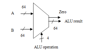
The ALU receives normally two values A and B, in this case, each 64 bits wide and it has 4 bits of control called ALU operation (Figure 4.7b in p.265). It will output the result as ALU result (64 bits) and also a 1 bit Zero output if the result of the operation is zero. See the Table below. This is similar to the Table on p.271 in the text. We are simulating the LEGv8 ALU for a small subset (say only 6) of the original ARMv8 ALU instructions. The actual ARM processor has more than 100 instructions. If there are 6 operations, the ALU operation bits need to be only 3 (to give 23 = 8 options) but the book uses 4 bits to have more options. (We will not use all the 4 bit combinations in our simple LEGv8 processor).
| ALU operation | Function | ALU result |
| 0000 | AND | A & B |
| 0001 | OR | A | B |
| 0010 | ADD | A + B |
| 0110 | SUBTRACT | A - B |
| 0111 | PASS INPUT B | B |
| 1100 | NOR | ~(A | B) |
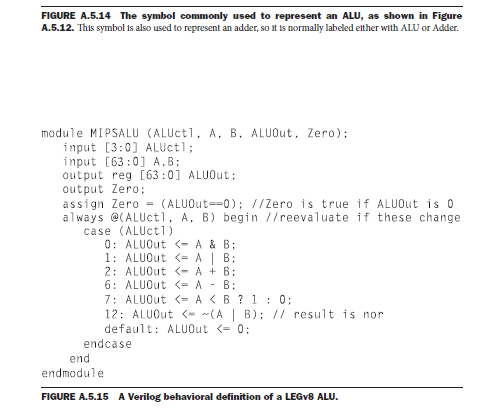
Modify the code given in p. A 36, Figure A.5.15 for the ALU module. For example, the first line should read
module LEGv8 (ALU operation, A, B, ALU result, Zero); Change the signal names ALUctl to ALU operation, ALUOut to ALU result. When the case is 7, the ALU result is simply B.
Develop a Verilog Test Fixture for testing it (New Source associated with lab2 project see lab 1 handout). You may initialize A and B as 64h5555555555555555 and 64haaaaaaaaaaaaaaaa. Remember these are antithetical. Results will be easy to check. Apply stimuli at different time slots to exercise the ALUs different functions. Give the 6 possible values for ALU operation and check whether ALU result tallies with theory. You can right click on the signal in the column left to the waveform in the simulation to change the radix from binary to hex. Check the Zero output also. Can you justify the result for the Subtract operation? The last hex value is b. A bit strange? Work out the subtract operation, say for the last two hex values and explain to the instructor what happened.
CECS 341 Lab 2B Simulation of the ALU Control Logic
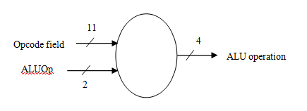
Objective: We want to simulate the combinational logic that develops the output ALU operation with the inputs ALUOp and Opcode field (I (31..21) as shown in the Table below (Figure 4.13 on p.273 in the text).
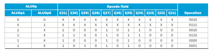
You may be tempted to use the code given in the appendix (p.A-37, Figure A.5.16) but it has some errors. We need to correct them. The always statement is not complete. It should be always @ (ALUOp, Opcode field) and then the case statement should follow. The case statements below should have values of the catenation of ALUOp and Opcode field (not just ALUOp). The switch values for the case statements given on the left extreme in decimal such as 32 are wrong. The values are 13 bits strong. You may use the table values with dont cares changed to zeros. After the switch values, the left side of assignment statements such as ALUOp
Example for OR entry:
13b10_10101010000: ALU operation
Make all the corrections needed. Then develop a Verilog Test Fixture and check whether ALU operation comes out as expected. We can test only the bottom four cases in the table for the time being.
CECS 341 - Lab 2C - Simulation of the ALU with its Control Logic
Objective: Now we want to combine ALU and the Control Logic. We will apply the inputs to the control logic and the ALU and see whether the combined module works right. ALU operation will become wire (it was input in 2A and output in 2B).
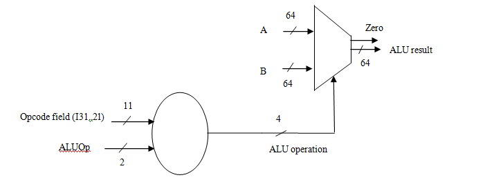
For the combined module, after the module statement with its port list and after declaring the inputs and outputs, declare ALU operation as wire. We must instantiate (give instances of) the two modules with arbitrary names but with proper connectivity. See below. Lab2b and Lab2a are the arbitrary instance names. They could have been anything, say second and first or something else.
module ALUwithControl (ALUOp, Opcode field, A, B, ALU result, Zero);
//Declare inputs and outputs and intermediate wires
input [1:0] ALUOp;
input [10:0] Opcode field;
input [63:0] A;
input [63:0] B;
output [63:0] ALU result;
output Zero;
wire [3:0] ALU operation;
//Instantiate the two units
ALUControl Lab2b (ALUOp, Opcode field, ALU operation);
ALU Lab2a (ALU operation, A, B, ALU result, Zero);
endmodule
Develop a Verilog test fixture and check whether ALU result comes out right for different ALUOp and Opcode field.
In the waveform, we may like to see ALU operation also but the simulator by default shows only the inputs and outputs of the combined module. We can add any intermediate signal to the waveform by going to the Simulation Hierarchy window (Instances and Processes tab at the bottom) and expanding the + sign next to module name (say, uut). Right click on the signal of interest and choose Add to waveform. The signal will not have any changes yet because we have to rerun the simulation. Click on the Restart Simulation Icon. In the console, type run 1000 ns and press enter. Check whether ALU operation became 2, 6 etc.
mc,s18
64 Zero ALU result 64 64 ALU operation 64 Zero ALU result 64 64 ALU operationStep by Step Solution
There are 3 Steps involved in it
Step: 1

Get Instant Access to Expert-Tailored Solutions
See step-by-step solutions with expert insights and AI powered tools for academic success
Step: 2

Step: 3
Ace Your Homework with AI
Get the answers you need in no time with our AI-driven, step-by-step assistance
Get Started
Formal SQL Tuning For Oracle Databases Practical Efficiency Efficient Practice
Authors: Leonid Nossov ,Hanno Ernst ,Victor Chupis
1st Edition
3662570564, 978-3662570562