Please write a code to comply with the MSP4302553.
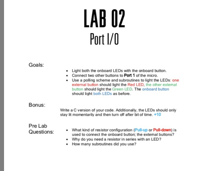
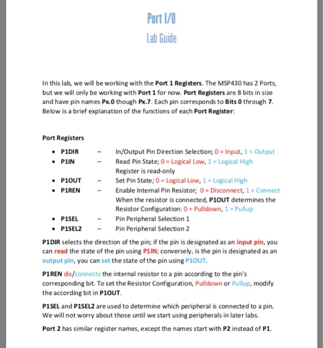
LAB 02 Port l/0 Goals: Light both the onboard LEDs with the onboard button Connect two other buttons to Port 1 of the micro. Use a polling scheme and subroutines to light the LEDs: one external button should light the Red LED, the other extemal button should light the Green LED. The onboard button should light both LEDs as before. Bonus: Write a C version of your code. Additionally, the LEDs should only stay lit momentarily and then turn off after bit of time. +10 Pre Lab Questions:.What kind of resistor configuration (Pull-up or Pull-down) is used to connect the onboard button; the extemal buttons? Why do you need a resistor in series with an LED? How many subroutines did you use? Port I/0 Lab Guide In this lab, we will be working with the Port 1 Registers. The MSP430 has 2 Ports, but we will only be working with Port 1 for now. Port Registers are 8 bits in size and have pin names Px.0 though Px.7. Each pin corresponds to Bits 0 through 7 Below is a brief explanation of the functions of each Port Register: Port Registers P1DIR PIIN In/Output Pin Direction Selection; 0 # Input, 1 Output Read Pin State; 0 Logical Low, 1-Logical High Register is read-only Set Pin State: 0-Logical Low, 1 0gical High Enable Internal Pin Resistor; 0 Disconnect, 1 Connect When the resistor is connected, P1OUT determines the Resistor Configuration:0-Pulldown, 1-Pullup P1OUT P1REN PISEL -Pin Peripheral Selection 1 -Pin Peripheral Selection 2 P1SEL2 P1DIR selects the direction of the pin; if the pin is designated as an input pin, you can read the state of the pin using P1IN; conversely, is the pin is designated as an output pin, you can set the state of the pin using P1OUT P1REN dis/connects the internal resistor to a pin according to the pin's corresponding bit. To set the Resistor Configuration, Pulldown or Pullup, modify the according bit in P1OUT P1SEL and P1SEL2 are used to determine which peripheral is connected to a pin. We will not worry about those until we start using peripherals in later labs. Port 2 has similar register names, except the names start with P2 instead of P1 LAB 02 Port l/0 Goals: Light both the onboard LEDs with the onboard button Connect two other buttons to Port 1 of the micro. Use a polling scheme and subroutines to light the LEDs: one external button should light the Red LED, the other extemal button should light the Green LED. The onboard button should light both LEDs as before. Bonus: Write a C version of your code. Additionally, the LEDs should only stay lit momentarily and then turn off after bit of time. +10 Pre Lab Questions:.What kind of resistor configuration (Pull-up or Pull-down) is used to connect the onboard button; the extemal buttons? Why do you need a resistor in series with an LED? How many subroutines did you use? Port I/0 Lab Guide In this lab, we will be working with the Port 1 Registers. The MSP430 has 2 Ports, but we will only be working with Port 1 for now. Port Registers are 8 bits in size and have pin names Px.0 though Px.7. Each pin corresponds to Bits 0 through 7 Below is a brief explanation of the functions of each Port Register: Port Registers P1DIR PIIN In/Output Pin Direction Selection; 0 # Input, 1 Output Read Pin State; 0 Logical Low, 1-Logical High Register is read-only Set Pin State: 0-Logical Low, 1 0gical High Enable Internal Pin Resistor; 0 Disconnect, 1 Connect When the resistor is connected, P1OUT determines the Resistor Configuration:0-Pulldown, 1-Pullup P1OUT P1REN PISEL -Pin Peripheral Selection 1 -Pin Peripheral Selection 2 P1SEL2 P1DIR selects the direction of the pin; if the pin is designated as an input pin, you can read the state of the pin using P1IN; conversely, is the pin is designated as an output pin, you can set the state of the pin using P1OUT P1REN dis/connects the internal resistor to a pin according to the pin's corresponding bit. To set the Resistor Configuration, Pulldown or Pullup, modify the according bit in P1OUT P1SEL and P1SEL2 are used to determine which peripheral is connected to a pin. We will not worry about those until we start using peripherals in later labs. Port 2 has similar register names, except the names start with P2 instead of P1