

Answered step by step
Verified Expert Solution
Question
1 Approved Answer
pls solve correctly in matlab as soon as possible as this task worth a lot. The seven-segment LED Qight Emitting Diode) or LCD (Liquid Crystal
pls solve correctly in matlab as soon as possible as this task worth a lot.
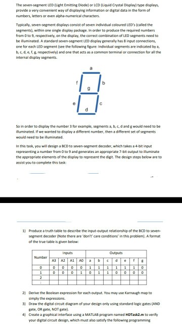
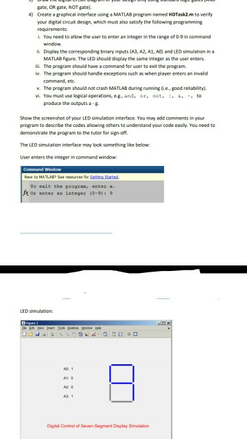
The seven-segment LED Qight Emitting Diode) or LCD (Liquid Crystal Display) type displays, provide a very convenient way of displaying information or digital data in the form of numbers, letters or even alpha-numerical characters Typically, seven-segment displays consist of seven individual coloured LED's (called the segments), within one single display package, in order to produce the required numbers from O to 9, respectively, on the display, the correct combination of LED segments need to be iluminated. A standard seven-segment LED display generally has 8 input connections one for each LED segment (see the folowing figure: Individuel segments are indicated by a, b, t, d, e, f, E respectively) and one that acts as a common terminal or connection for all the internal display segments So in order to display the number 3 for example, segments a, b, c,d and g would need to be illuminated. If we wanted to display a different number, then a different set of segments would need to be iluminated. In this task, you will design a BCD to seven-segment decoder, which takes a 4-bit input representing a number from O to 9 and generates an appropriate 7-bit output to illuminate the appropriate elements of the display to represent the digt. The design steps below are to assist you to complete this task: Produce a truth table to describe the input-output relationship of the BCD to seven- segment decoder (Note there are 'don't' care conditions' in this problem).A format of the true table is given below Inputs Outputs 21 Derive the Boolean expression for each output. You may use Karnaugh map to 3 Oraw the digital circuit diagram of your design only using standard logic gates (AND 4l imply the expressions. eate, OR gate, NOT gate) Create a graphical interface using a MATLAB program named HDTask2.m to verify your digital circuit design, which must also satisfy the following programmingStep by Step Solution
There are 3 Steps involved in it
Step: 1

Get Instant Access to Expert-Tailored Solutions
See step-by-step solutions with expert insights and AI powered tools for academic success
Step: 2

Step: 3
Ace Your Homework with AI
Get the answers you need in no time with our AI-driven, step-by-step assistance
Get Started
Marketing Database Analytics
Authors: Andrew D. Banasiewicz
1st Edition
0415657881, 978-0415657884