 plz help w what u can
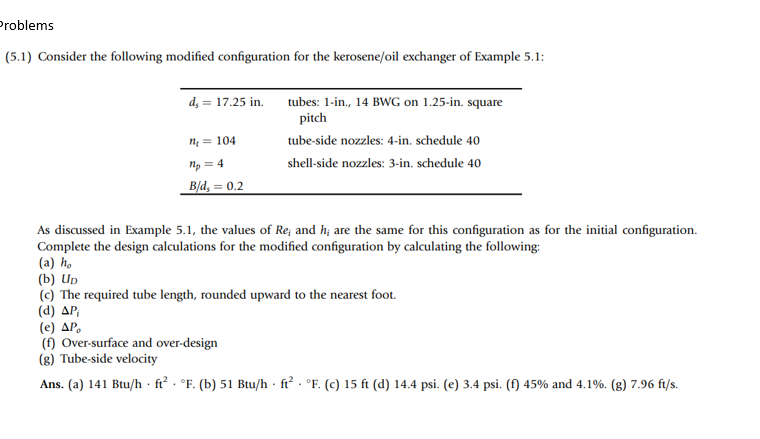
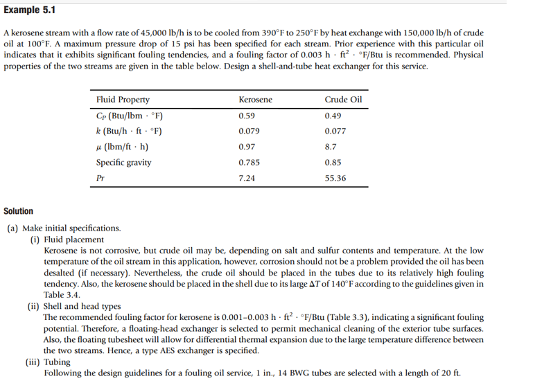
5.1) Consider the following modified configuration for the kerosene/oil exchanger of Example 5.1: As discussed in Example 5.1, the values of Rei and hi are the same for this configuration as for the initial configuration. Complete the design calculations for the modified configuration by calculating the following: (a) ho (b) UD (c) The required tube length, rounded upward to the nearest foot. (d) Pi (e) Po (f) Over-surface and over-design (g) Tube-side velocity Ans. (a) 141Btu/hft2F. (b) 51Btu/hft2F. (c) 15ft (d) 14.4psi. (e) 3.4psi. (f) 45% and 4.1%. (g) 7.96ft/s. A kerosene stream with a flow rate of 45,000lb/h is to be cooled from 390F to 250F by heat exchange with 150,000lb/h of crude oil at 100F. A maximum pressure drop of 15psi has been specified for each stream. Prior experience with this particular oil indicates that it exhibits significant fouling tendencies, and a fouling factor of 0.003hft2F/ Btu is recommended. Physical properties of the two streams are given in the table below. Design a shell-and-tube heat exchanger for this service. Solution (a) Make initial specifications. (i) Fluid placement Kerosene is not corrosive, but crude oil may be, depending on salt and sulfur contents and temperature. At the low temperature of the oil stream in this application, however, corrosion should not be a problem provided the oil has been desalted (if necessary). Nevertheless, the crude oil should be placed in the tubes due to its relatively high fouling tendency. Also, the kerosene should be placed in the shell due to its large T of 140F according to the guidelines given in Table 3.4. (ii) Shell and head types The recommended fouling factor for kerosene is 0.0010.003hft2F/Btu (Table 3.3), indicating a significant fouling potential. Therefore, a floating-head exchanger is selected to permit mechanical cleaning of the exterior tube surfaces. Also, the floating tubesheet will allow for differential thermal expansion due to the large temperature difference between the two streams. Hence, a type AES exchanger is specified. (iii) Tubing Following the design guidelines for a fouling oil service, 1 in., 14BWG tubes are selected with a length of 20ft. 5.1) Consider the following modified configuration for the kerosene/oil exchanger of Example 5.1: As discussed in Example 5.1, the values of Rei and hi are the same for this configuration as for the initial configuration. Complete the design calculations for the modified configuration by calculating the following: (a) ho (b) UD (c) The required tube length, rounded upward to the nearest foot. (d) Pi (e) Po (f) Over-surface and over-design (g) Tube-side velocity Ans. (a) 141Btu/hft2F. (b) 51Btu/hft2F. (c) 15ft (d) 14.4psi. (e) 3.4psi. (f) 45% and 4.1%. (g) 7.96ft/s. A kerosene stream with a flow rate of 45,000lb/h is to be cooled from 390F to 250F by heat exchange with 150,000lb/h of crude oil at 100F. A maximum pressure drop of 15psi has been specified for each stream. Prior experience with this particular oil indicates that it exhibits significant fouling tendencies, and a fouling factor of 0.003hft2F/ Btu is recommended. Physical properties of the two streams are given in the table below. Design a shell-and-tube heat exchanger for this service. Solution (a) Make initial specifications. (i) Fluid placement Kerosene is not corrosive, but crude oil may be, depending on salt and sulfur contents and temperature. At the low temperature of the oil stream in this application, however, corrosion should not be a problem provided the oil has been desalted (if necessary). Nevertheless, the crude oil should be placed in the tubes due to its relatively high fouling tendency. Also, the kerosene should be placed in the shell due to its large T of 140F according to the guidelines given in Table 3.4. (ii) Shell and head types The recommended fouling factor for kerosene is 0.0010.003hft2F/Btu (Table 3.3), indicating a significant fouling potential. Therefore, a floating-head exchanger is selected to permit mechanical cleaning of the exterior tube surfaces. Also, the floating tubesheet will allow for differential thermal expansion due to the large temperature difference between the two streams. Hence, a type AES exchanger is specified. (iii) Tubing Following the design guidelines for a fouling oil service, 1 in., 14BWG tubes are selected with a length of 20ft

 plz help w what u can


