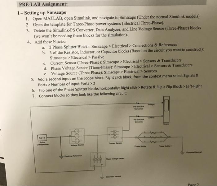
PRE-LAB Assignment: I - Setting up Simscape 1. Open MATLAB, open Simulink, and navigate to Simscape (Under the normal Simulink models) 2. Open the template for Three-Phase power systems (Electrical Three-Phase). 3. Delete the Simulink-PS Converter, Data Analyzer, and Line Voltage Sensor (Three-Phase) blocks (we won't be needing these blocks for the simulation). 4. Add these blocks: a. 2 Phase Splitter Blocks: Simscape > Electrical > Connections & References b. 3 of the Resistor, Inductor, or Capacitor blocks (Based on the circuit you want to construct): Simscape > Electrical > Passive c. Current Sensor (Three-Phase): Simscape > Electrical > Sensors & Transducers d. Phase Voltage Sensor (Three-Phase): Simscape > Electrical > Sensors & Transducers e. Voltage Source (Three-Phase): Simscape > Electrical > Sources 5. Add a second input on the scope block: Right click block, from the context menu select Signals & Ports > Number of Input Ports > 2 6. Flip one of the Phase Splitter blocks horizontally: Right click > Rotate & Flip > Flip Block > Left-Right 7. Connect blocks so they look like the following circuit: - Pron2 8. Specify simulation parameters: a. Solver Configuration block: select Use local solver and set Sample time to 0.0001 (based off what is an appropriate sample time for a 60 Hz AC system) b. In the Simulink Editor, set the simulation Stop time to 0.1 9. Set up display parameters: a. Set the PS-Simulink Converter blocks so that the output signal unit for one is and the other is A (double click on converter). b. Label the input signals for the scope as Voltages or Currents based on their input (double click on lines) c When simulating, go to Scope menu, select View > Configuration Properties and set Layout to 1 by 2 display 1 - Simulation of a Three-Phase Purely Resistive Load 1. Set all three resistor values to 12000 and set the Voltage Source block to 100 V RMS 2. Hit the Run button at the top of the page and double click on the Scope to see the data collected. What does the scope tell us about the power system? (Paste a screenshot of your scope output below) 3. Set one of the resistors to 2000 and run the simulation. What does this tell us about unbalanced systems? (Paste a screenshot of your scope output below) 11 - Simulation of a Three-Phase Purely Inductive Load 4. Sketch a three-phase 100 V RMS phase-voltage, Wye (Y) Connected power supply with a Wye (Y) Connected load with purely inductive j3002 per phase. Then create the same system in Simscape. 5. Assume the phase-voltage of phase-A at the source side has an angle of zero. Calculate both magnitudes and phase-angles for phase voltage, line voltage, phase current, and line current at the load side. Also, compute load real power, apparent Power, and power factor. Compare this to the output of the Scope from your simulation. Values Quantity V.M Vuine (V) (A) ILine (A) P (W) S (VA) P.F. (lagging or leading) PRE-LAB Assignment: I - Setting up Simscape 1. Open MATLAB, open Simulink, and navigate to Simscape (Under the normal Simulink models) 2. Open the template for Three-Phase power systems (Electrical Three-Phase). 3. Delete the Simulink-PS Converter, Data Analyzer, and Line Voltage Sensor (Three-Phase) blocks (we won't be needing these blocks for the simulation). 4. Add these blocks: a. 2 Phase Splitter Blocks: Simscape > Electrical > Connections & References b. 3 of the Resistor, Inductor, or Capacitor blocks (Based on the circuit you want to construct): Simscape > Electrical > Passive c. Current Sensor (Three-Phase): Simscape > Electrical > Sensors & Transducers d. Phase Voltage Sensor (Three-Phase): Simscape > Electrical > Sensors & Transducers e. Voltage Source (Three-Phase): Simscape > Electrical > Sources 5. Add a second input on the scope block: Right click block, from the context menu select Signals & Ports > Number of Input Ports > 2 6. Flip one of the Phase Splitter blocks horizontally: Right click > Rotate & Flip > Flip Block > Left-Right 7. Connect blocks so they look like the following circuit: - Pron2 8. Specify simulation parameters: a. Solver Configuration block: select Use local solver and set Sample time to 0.0001 (based off what is an appropriate sample time for a 60 Hz AC system) b. In the Simulink Editor, set the simulation Stop time to 0.1 9. Set up display parameters: a. Set the PS-Simulink Converter blocks so that the output signal unit for one is and the other is A (double click on converter). b. Label the input signals for the scope as Voltages or Currents based on their input (double click on lines) c When simulating, go to Scope menu, select View > Configuration Properties and set Layout to 1 by 2 display 1 - Simulation of a Three-Phase Purely Resistive Load 1. Set all three resistor values to 12000 and set the Voltage Source block to 100 V RMS 2. Hit the Run button at the top of the page and double click on the Scope to see the data collected. What does the scope tell us about the power system? (Paste a screenshot of your scope output below) 3. Set one of the resistors to 2000 and run the simulation. What does this tell us about unbalanced systems? (Paste a screenshot of your scope output below) 11 - Simulation of a Three-Phase Purely Inductive Load 4. Sketch a three-phase 100 V RMS phase-voltage, Wye (Y) Connected power supply with a Wye (Y) Connected load with purely inductive j3002 per phase. Then create the same system in Simscape. 5. Assume the phase-voltage of phase-A at the source side has an angle of zero. Calculate both magnitudes and phase-angles for phase voltage, line voltage, phase current, and line current at the load side. Also, compute load real power, apparent Power, and power factor. Compare this to the output of the Scope from your simulation. Values Quantity V.M Vuine (V) (A) ILine (A) P (W) S (VA) P.F. (lagging or leading)