

Answered step by step
Verified Expert Solution
Question
1 Approved Answer
Problem 1 (20 Points): Sketch the state transition diagram for the FSM described by the following SystemVerilog code. module fsm2 input logic clk, reset, input
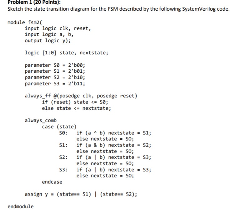
Problem 1 (20 Points): Sketch the state transition diagram for the FSM described by the following SystemVerilog code. module fsm2 input logic clk, reset, input logic a, b, output logic y); logic [1:0] state, nextstate; parameter se 2 'bee; parameter S1 = 2 'b01; parameter S2 = 2'b10; parameter S3 = 2'b11; always_ff @(posedge clk, posedge reset) if (reset) state
Step by Step Solution
There are 3 Steps involved in it
Step: 1

Get Instant Access to Expert-Tailored Solutions
See step-by-step solutions with expert insights and AI powered tools for academic success
Step: 2

Step: 3
Ace Your Homework with AI
Get the answers you need in no time with our AI-driven, step-by-step assistance
Get Started
Professional Microsoft SQL Server 2012 Administration
Authors: Adam Jorgensen, Steven Wort
1st Edition
1118106881, 9781118106884