Answered step by step
Verified Expert Solution
Question
1 Approved Answer
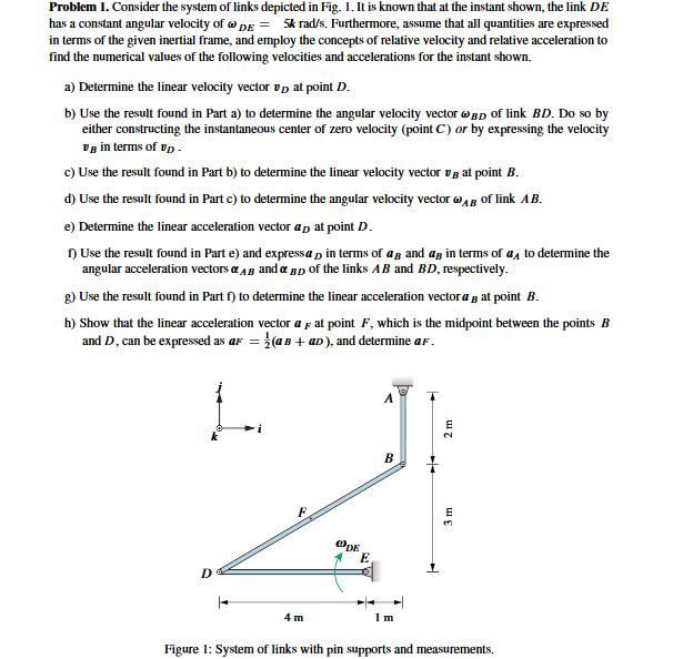
Problem 1. Consider the system of links depicted in Fig. 1. It is known that at the instant shown, the link DE has a

Problem 1. Consider the system of links depicted in Fig. 1. It is known that at the instant shown, the link DE has a constant angular velocity ofDE= 5k rad/s. Furthermore, assume that all quantities are expressed in terms of the given inertial frame, and employ the concepts of relative velocity and relative acceleration to find the numerical values of the following velocities and accelerations for the instant shown. a) Determine the linear velocity vector at point D. b) Use the result found in Part a) to determine the angular velocity vector BD of link BD. Do so by either constructing the instantaneous center of zero velocity (point C) or by expressing the velocity VB in terms of up c) Use the result found in Part b) to determine the linear velocity vector vat point B. d) Use the result found in Part c) to determine the angular velocity vector of link AB. e) Determine the linear acceleration vector ap at point D. f) Use the result found in Parte) and expressa in terms of an and a in terms of a to determine the angular acceleration vectors AB and BD of the links AB and BD, respectively. g) Use the result found in Part f) to determine the linear acceleration vector a at point B. h) Show that the linear acceleration vector af at point F, which is the midpoint between the points B and D, can be expressed as a = (aB+ aD), and determine af. D P 4 m ODE E A B 1 m 2 m 3 m 3 Figure 1: System of links with pin supports and measurements.
Step by Step Solution
There are 3 Steps involved in it
Step: 1

Get Instant Access to Expert-Tailored Solutions
See step-by-step solutions with expert insights and AI powered tools for academic success
Step: 2

Step: 3

Ace Your Homework with AI
Get the answers you need in no time with our AI-driven, step-by-step assistance
Get Started


