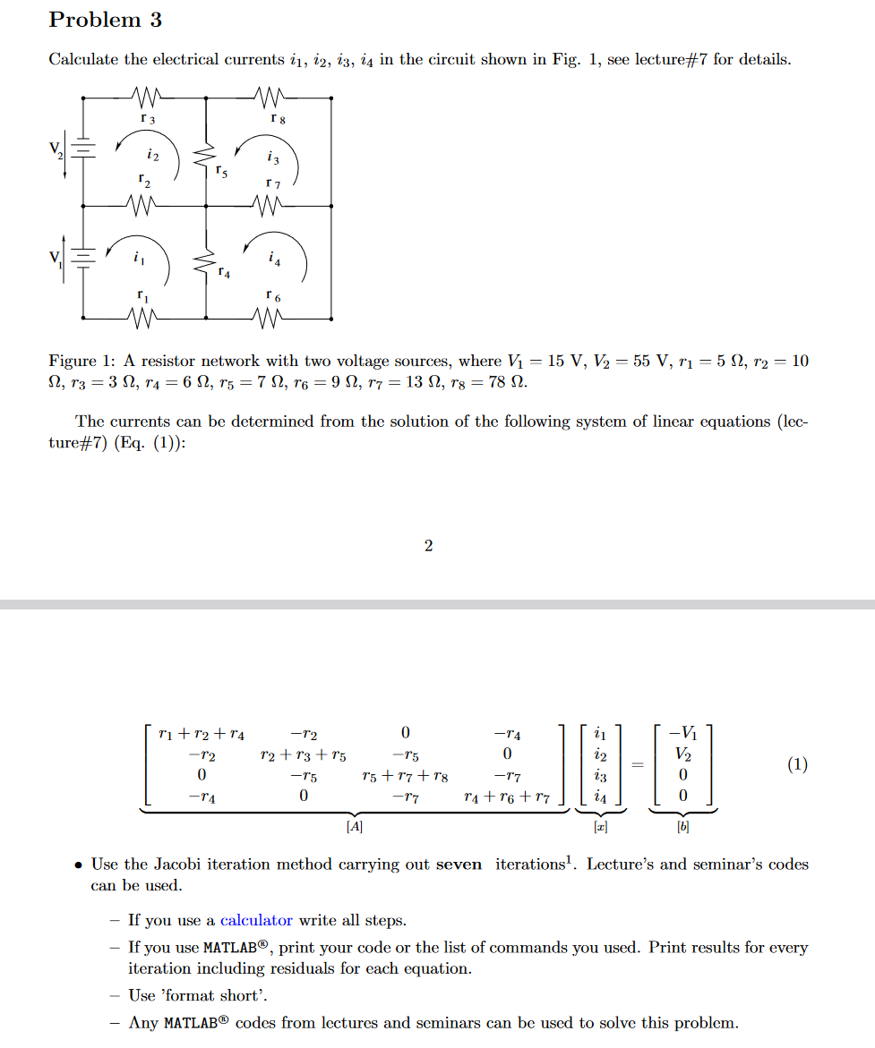
Question: Problem 3 Calculate the electrical currents i1, 12, 13, 14 in the circuit shown in Fig. 1, see lecture #7 for details. r3 [

Problem 3 Calculate the electrical currents i1, 12, 13, 14 in the circuit shown in Fig. 1, see lecture #7 for details. r3 [ 18 17 n Figure 1: A resistor network with two voltage sources, where V = 15 V, V = 55 V, r= 5 N, T = 10 N, T3 = 3 , r4 = 6 N, T5 = 7, r6 = 9, r7 = 13 N, rg = 78 N. r+1+r4 -12 0 -TA The currents can be determined from the solution of the following system of linear equations (lec- ture#7) (Eq. (1)): -72 12 +13 +r5 -75 0 2 0 -75 75+77 +78 -77 -T4 0 -17 r4 +r6+r7 24 [T] 0 (1) [A] [b] Use the Jacobi iteration method carrying out seven iterations. Lecture's and seminar's codes can be used. - If you use a calculator write all steps. If you use MATLAB, print your code or the list of commands you used. Print results for every iteration including residuals for each equation. Use 'format short'. Any MATLAB codes from lectures and seminars can be used to solve this problem.
Step by Step Solution
3.57 Rating (150 Votes )
There are 3 Steps involved in it
To solve for the electrical currents i1 i2 i3 i4 in the circuit we are given a system of linear equations that can be represented in matrix form Given ... View full answer

Get step-by-step solutions from verified subject matter experts


