

Question
Problem 3: Using Verilog, design the module diagram shown in the next page. The results S2, S1, and S0 will be taken as input codes
Problem 3: Using Verilog, design the module diagram shown in the next page.
The results S2, S1, and S0 will be taken as input codes to the BCD-to-Seven Segment Display modules. The outputs HEX2, HEX1, and HEX0 will drive the seven-segment displays.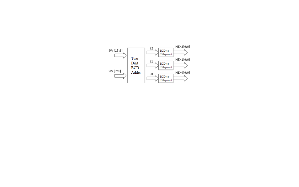
Step by Step Solution
There are 3 Steps involved in it
Step: 1

Get Instant Access to Expert-Tailored Solutions
See step-by-step solutions with expert insights and AI powered tools for academic success
Step: 2

Step: 3
Ace Your Homework with AI
Get the answers you need in no time with our AI-driven, step-by-step assistance
Get Started
Data Management Databases And Organizations
Authors: Watson Watson
5th Edition
0471715360, 978-0471715368