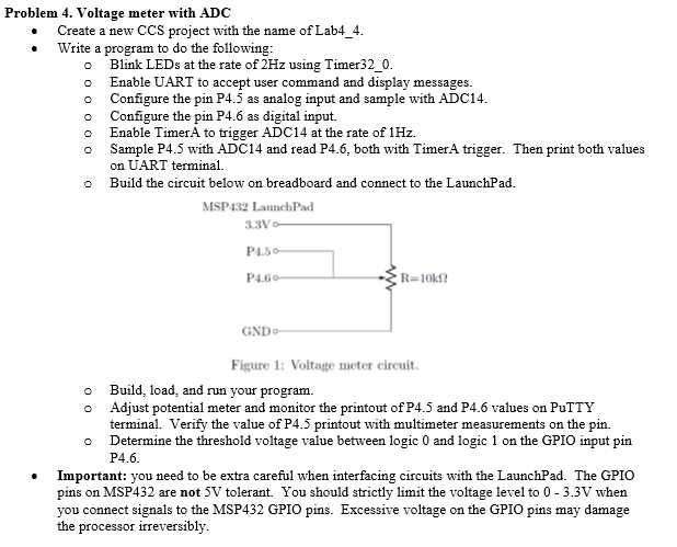
Problem 4. Voltage meter with ADC Create a new CCS project with the name of Lab4_4 Write a program to do the follo wing o Blink LEDs at the rate of 2Hz using Timer32_0 o Enable UART to accept user command and display messages o Configure the pin P4.5 as analog input and sample with ADC14 o Configure the pin P4.6 as digital input o Enable TimerA to trigger ADC14 at the rate of 1Hz. o Sample P4.5 with ADC14 and read P4.6, both with TimerA trigger. Then print both values on UART terminal. o Build the circuit below on breadboard and connect to the LaunchPad. MSP432 LaunchPad P1.5 P4.6 GND Figure 1: Voltage meter circuit. o Build, load, and run your program. o Adjust potential meter and monitor the printout of P4.5 and P4.6 values on PuTTY terminal. Verify the value of P4.5 printout with multimeter measurements on the pin. o Determine the threshold voltage value between logic 0 and logic 1 on the GPIO input pitn P4.6 Important: you need to be extra careful when interfacing circuits with the LaunchPad. The GPIO pins on MSP432 are not 5V tolerant You should strictly limit the voltage level to 0 - 3.3V when you connect signals to the MSP432 GPIO pins. Excessive voltage on the GPIO pins may damage the processor irreversibly Problem 4. Voltage meter with ADC Create a new CCS project with the name of Lab4_4 Write a program to do the follo wing o Blink LEDs at the rate of 2Hz using Timer32_0 o Enable UART to accept user command and display messages o Configure the pin P4.5 as analog input and sample with ADC14 o Configure the pin P4.6 as digital input o Enable TimerA to trigger ADC14 at the rate of 1Hz. o Sample P4.5 with ADC14 and read P4.6, both with TimerA trigger. Then print both values on UART terminal. o Build the circuit below on breadboard and connect to the LaunchPad. MSP432 LaunchPad P1.5 P4.6 GND Figure 1: Voltage meter circuit. o Build, load, and run your program. o Adjust potential meter and monitor the printout of P4.5 and P4.6 values on PuTTY terminal. Verify the value of P4.5 printout with multimeter measurements on the pin. o Determine the threshold voltage value between logic 0 and logic 1 on the GPIO input pitn P4.6 Important: you need to be extra careful when interfacing circuits with the LaunchPad. The GPIO pins on MSP432 are not 5V tolerant You should strictly limit the voltage level to 0 - 3.3V when you connect signals to the MSP432 GPIO pins. Excessive voltage on the GPIO pins may damage the processor irreversibly


