Question
Problem 8: (35 points) This semester you will realize a Moore finite state machine for controlling a garage door opener using four different design tools:
Problem 8: (35 points) This semester you will realize a Moore finite state machine for controlling a garage door opener using four different design tools:
Discrete logic using NAND gates and D-type flip-flops
The myDAQ using the LabVIEW programming environment
An embedded microcontroller programmed using the C programming language
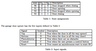
This problem provides design specifications and requires you to represent the finite state machine using a state diagram and state table. The finite state machine has four states defined in Table 1.

The top and bottom signals are generated by mechanical limitswitches that indicate when the door is either completed opened or closed. An infrared light beam directed across the doorway detects obstacles in the path of the garage door. When an obstacle breaks the beam the signal P is false. The user opens and closes the garage door by pressing a control button that generates the signal C. While the signals T, B, P and C are observed synchronously with respect to a 10 Hz clock signal, the input R is an asynchronous input. When R is set true, the system must immediately stop the door by entering state S0. The finite state machine generates two output signals, up (U) and down (D) that control the garage door motor as shown in Table 3. The output signals U and D must never be true at the same time to avoid damaging the motor.

The design specifications for the garage door controller are as follows.
Use a clock rate of 10 Hz so that the system quickly responds to changes in the photodetector signal P, to avoid injury, and to changes in T and B, to avoid damaging the motor when the door reaches a mechanical limit.
If the door was previously stopped while closing, pressing the control button (C = 1) causes the door to begin opening.
When the door reaches the top (T = 1) while opening, the motor must stop.
If the door was previously stopped while opening, pressing the button (C = 1) causes the door to begin closing.
When the door reaches the bottom (B = 1) while closing, the motor must stop.
If the infrared beam detects an obstacle in the doorway (P = 0) while the door is closing, the system must enter state S0 so that the door stops, regardless of the values of the other inputs.
If the infrared beam detects an obstacle in the doorway (P = 0) while the door is opening, the door must continue to open.
Pressing the control button (C = 1) while the door is opening causes the door to stop. Pressing the button again (C = 1) causes the door to begin closing.
Pressing the button (C = 1) while the door is closing causes the door to stop. Pressing the button again (C = 1) causes the door to begin opening.
If the reset signal is true (R = 1), the system must asynchronously return to state S0.
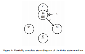
1. (9 points) Complete the state diagram of the finite state machine for the garage door opener in Figure 1. If an input does not affect the transition from one state to the next, it should not be listed. For example, while in state S0, regardless of the values of the inputs T, B, or P, if C = 0, the system must remain in state S0, and if C = 1, the system must transition to state S1

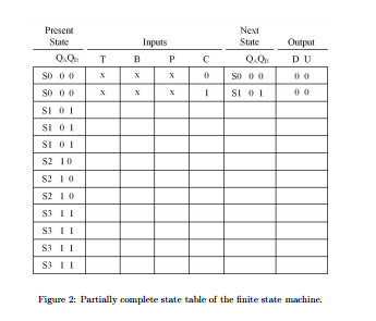
2. (16 points) The first two lines of the state table in Figure 2 are completed. Because there are four binary input signals, for each state there are sixteen possible combinations of input values T, B, or P, and C that can determine the next state. As there are four states, the complete state table must have sixty-four lines. Fortunately, it is possible to reduce the number of lines in the state table by taking into account that not all the inputs play a role in determining the next state. As an example, consider the first line of the state table. When the system is in state S0, regardless of the values of the inputs T, B, and P, if C = 0, the next state must be S0. As the values of these inputs may be either 0 or 1, their value is indicated by x. It follows that when in state S0, regardless of the eight possible combinations of input values for T, B, and P, as long as C = 0, the next state is S0. Complete the state table, noting that three lines are required for both states S1 and S2, while four lines are required for state S3. Figure 2: Partially complete state table of the finite state machine.

Step by Step Solution
There are 3 Steps involved in it
Step: 1

Get Instant Access to Expert-Tailored Solutions
See step-by-step solutions with expert insights and AI powered tools for academic success
Step: 2

Step: 3

Ace Your Homework with AI
Get the answers you need in no time with our AI-driven, step-by-step assistance
Get Started


