

Answered step by step
Verified Expert Solution
Question
1 Approved Answer
Problem: Write a Verilog code that starts at 0 and increments to 9 on a seven segment PMOD display that uses both PMODA and PMODB
Problem: Write a Verilog code that starts at and increments to on a seven segment PMOD display that uses both PMODA and PMODB on the PYNQZ FPGA development board. Zynq
I have been struggling to get the counter to work. I have successfully got each number to display on the seven segment, but I can not get a loop to work. I have added buttons and switches, but they do not make the problem better. Does someone have an idea as to where I can improve my code?
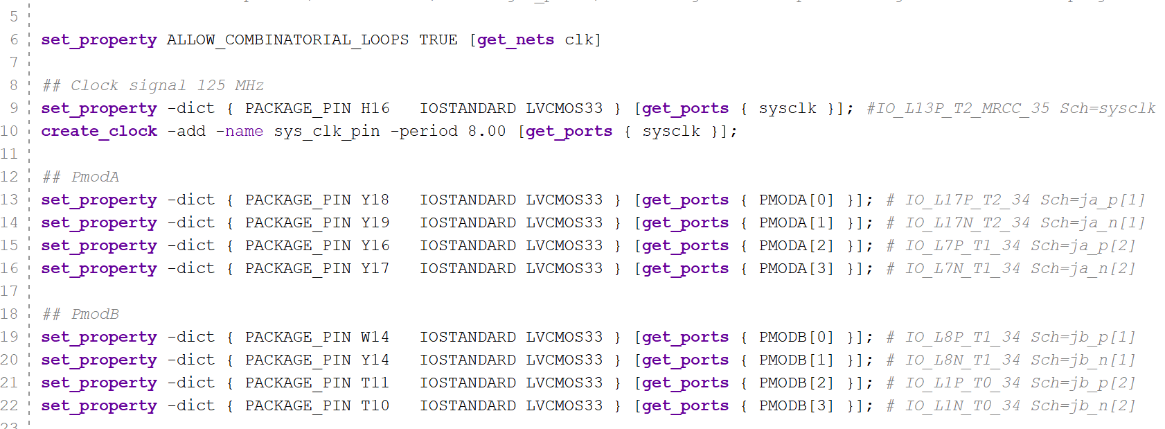
Constraint file:
setproperty ALLOWCOMBINATORIALLOOPS TRUE getnets clk
## Clock signal MHz
setproperty dict PACKAGEPIN H IOSTANDARD LVCMOSgetports sysclk ; #IOLPTMRCC SChSYSCIk
createclock add name sysclkpin period getports sysclk ;
## PmodA
setproperty dict PACKAGEPIN Y IOSTANDARD LVCMOSgetports PMODA; # IOIIPT SChjap
setproperty dict PACKAGEPIN Y IOSTANDARD LVCMOSgetports PMODA; #IOLNT SChjan
setproperty dict PACKAGEPIN Y IOSTANDARD LVCMOSgetports PMODA; # IOIPTI SChjap
setproperty dict PACKAGEPIN Y IOSTANDARD LVCMOSgetports PMODA; # IOLNTI SChjan
## PmodB
setproperty dict PACKAGEPIN W IOSTANDARD LVCMOSgetports PMODB; # IOLPT SChjbp
setproperty dict PACKAGEPIN Y IOSTANDARD LVCMOSgetports PMODB; # IOLNT SChjbn
setproperty dict PACKAGEPIN T IOSTANDARD LVCMOSgetports PMODB; # IOLIPTO SChjbp
setproperty dict PACKAGEPIN T IOSTANDARD LVCMOSgetports PMODB; # IOIINTO SChjbn
Source Code:
module SevenSegement
output reg : PMODB,
output reg : PMODA
;
reg : segvalues :;
reg : counter;
reg clk;
reg : delaycounter;
initial begin
Initialize clock to
clk ;
segvaluesb;
segvaluesb;
segvaluesb;
segvaluesb;
segvaluesb;
segvaluesb;
segvaluesb;
segvaluesb;
segvaluesb;
segvaluesb;
Set clock frequency to MHz
#;
Start the delay counter
delaycounter ;
end
always # clk ~clk; Toggle clock every time unit
always @posedge clk begin
Increment the counter
if delaycounter
counter counter ;
Reset the counter if it reaches
if counter
counter ;
Increment the delay counter
delaycounter delaycounter ;
end
always @ begin
Assign segment values based on the counter
PMODA PMODB segvaluescounter;
Reset the delay counter after seconds MHz clock assumed
if delaycounter
delaycounter ;
end
endmodule
We are using Vivado Software
Step by Step Solution
There are 3 Steps involved in it
Step: 1

Get Instant Access to Expert-Tailored Solutions
See step-by-step solutions with expert insights and AI powered tools for academic success
Step: 2

Step: 3
Ace Your Homework with AI
Get the answers you need in no time with our AI-driven, step-by-step assistance
Get Started
Microsoft Word 365 2022 Beginners Guide A Comprehensive User Guide For Beginners And Seniors With Tips And Tricks To Master Word 365
Authors: Howard J Wall
1st Edition
B0B1MGTGQ5, 979-8829667160