

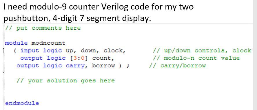
Question: Provide modulo-9 counter Verilog code for two push buttons display. sdc file // put comments here module modncount ( input logic up, down, clock, //
Provide modulo-9 counter Verilog code for two push buttons display.
![// up/down controls, clock output logic [3:0] count, // modulo-9 count value](https://dsd5zvtm8ll6.cloudfront.net/si.experts.images/questions/2024/09/66ef8959b8acf_29766ef895930c6b.jpg)
sdc file
// put comments here
module modncount ( input logic up, down, clock, // up/down controls, clock output logic [3:0] count, // modulo-9 count value output logic carry, borrow ) ; // carry/borrow
// your solution goes here
endmodule
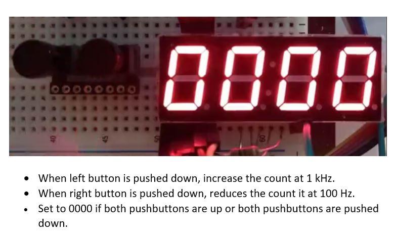
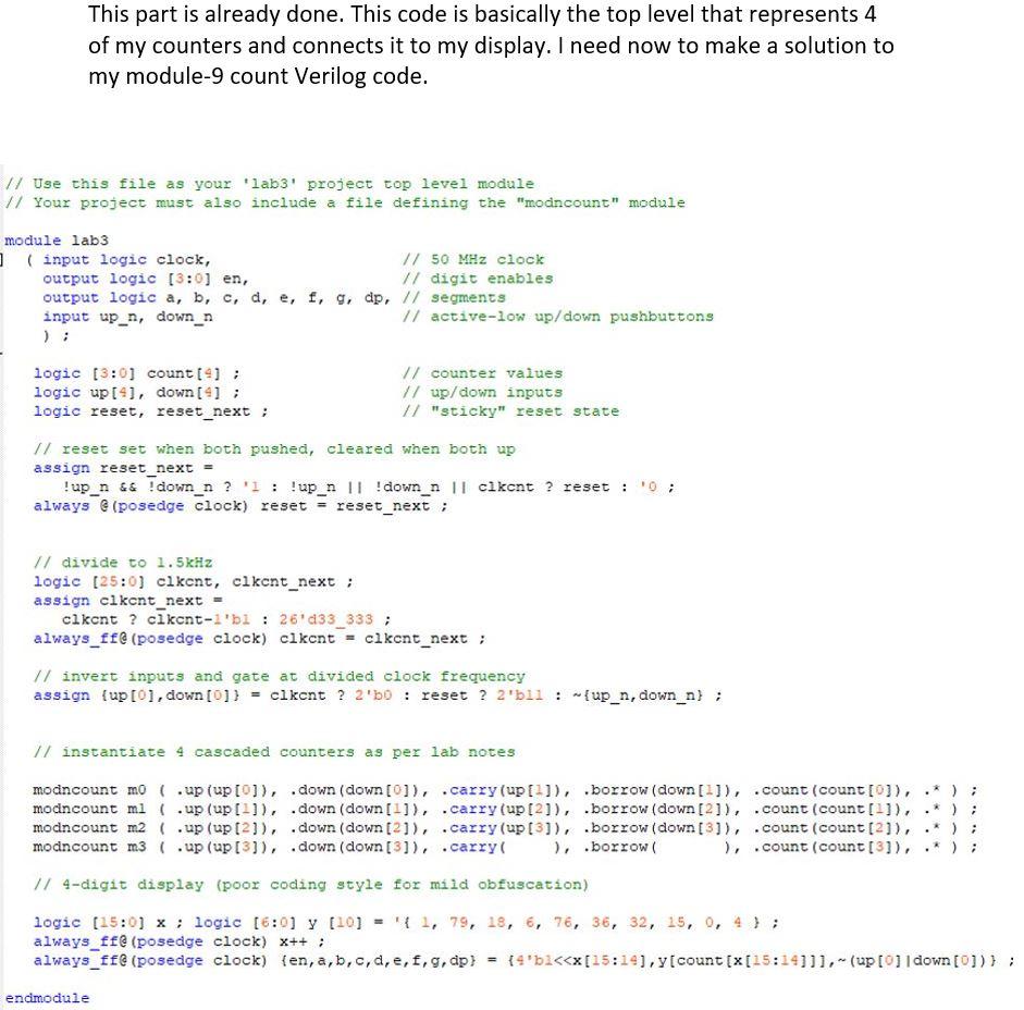
I need modulo-9 counter Verilog code for my two pushbutton, 4-digit 7 segment display. // put comments here module modncount 1 ( input logic up, down, clock, output logic (3:0) count, output logic carry, borrow ) ; // up/down controls, clock // modulo-n count value // carry/borrow // your solution goes here endmodule 0008 S When left button is pushed down, increase the count at 1 kHz. When right button is pushed down, reduces the count it at 100 Hz. Set to 0000 if both pushbuttons are up or both pushbuttons are pushed down. . The connections to the CPLD are shown in the fol- lowing diagram: lab5 en (3:0) 4 en(3) en(0) up_n D1 D2 D3 D4 LD5643BR abcdefg down_n 200 x 7 7 a,b... out out b out out d out dp out e out out Assignment Name Location Location Location Location Location Location Location Location Location Location Location Location Location Location Location Weak Pull-Up Resistor Weak Pull-Up Resistor en[3] en[2] en[1] en[0] f Value PIN_33 PIN_44 PIN_38 PIN_34 PIN_36 PIN_30 PIN_35 PIN_50 PIN_48 PIN_42 PIN_52 PIN_40 PIN_12 PIN_99 PIN_97 On out out out out in 8 clock in up_n down_n up_n down_n On This part is already done. This code is basically the top level that represents 4 of my counters and connects it to my display. I need now to make a solution to my module-9 count Verilog code. // Use this file as your 'labs' project top level module // Your project must also include a file defining the "modncount" module module lab3 ] (input logic clock, // 50 MHz clock output logic (3:0) en, // digit enables output logic a, b, c, d, e, f, g, dp, // segments input up_n, down_n // active-low up/down pushbuttons logic (3:0) count(); logic up[4], down[9]; logic reset, reset_next; // counter values // up/down inputs // "sticky" reset state // reset set when both pushed, cleared when both up assign reset_next = ! up_n && ! down_n? ': !up_n || ! down_n 11 cikcnt ? reset : always @ (posedge clock) reset = reset_next; 0; // divide to 1.5kHz logic (25:0) clkent, clkent_next; assign clkont_next clkent ? ckcnt-i'bi : 26'd33_333 ; always_ff@ (posedge clock) clkent = clkent_next; // invert inputs and gate at divided clock frequency assign {up [0], down[0]) = clkent ? 2'50 : reset ? 2'bll: {up_n, down_n) ; // instantiate 4 cascaded counters as per lab notes . modncount mo ( .up (up[0]), .down (down[0]), .carry(up [1]), borrow (down[1]), .count (count [0]), modncount ml ( .up (up[-]), .down (down[1]), .carry (up [2]), borrow (down [2]), .count (count[?]), modncount m2 .up (up [2]), .down (down (21), .carry (up [3]), borrow (down[3]), .count(count [2]), modncount m3 ( .up (up[3]), .down (down[3]), .carry ), borrow ), .count (count [3]). // 4-digit display (poor coding style for mild obfuscation) logic (15:0) x ; logic (6:0) y (10) = { 1, 79, 18, 6, 7, 36, 32, 15, 0, 4); always_f@ (posedge clock) x++; always_ff (posedge clock) {en, a, b, c, d, e, f, g, dp) = {4'b2
Step by Step Solution
There are 3 Steps involved in it

Get step-by-step solutions from verified subject matter experts