Answered step by step
Verified Expert Solution
Question
1 Approved Answer
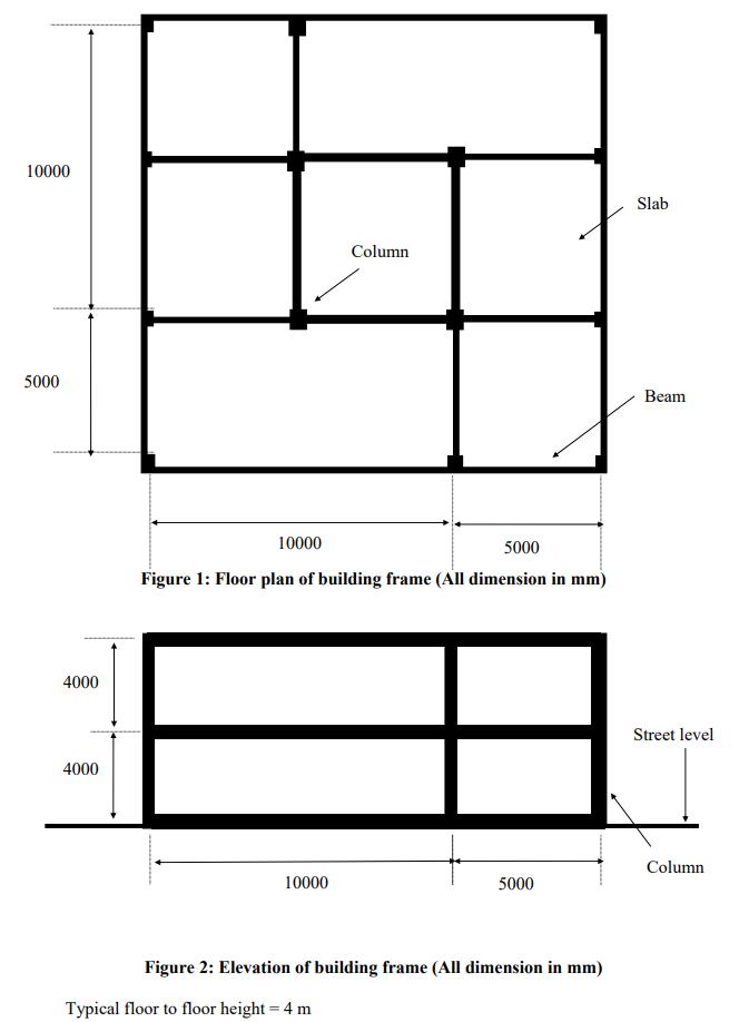
Provide the required bending moment, shear and axial force diagrams for the beams, slabs and columns. 10000 5000 4000 4000 Column Slab 10000 5000


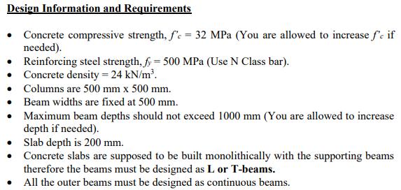
Provide the required bending moment, shear and axial force diagrams for the beams, slabs and columns. 10000 5000 4000 4000 Column Slab 10000 5000 Figure 1: Floor plan of building frame (All dimension in mm) 10000 Beam Street level Column 5000 Figure 2: Elevation of building frame (All dimension in mm) Typical floor to floor height = 4 m Design Information and Requirements Concrete compressive strength, f'c = 32 MPa (You are allowed to increase fe if needed). Reinforcing steel strength, f = 500 MPa (Use N Class bar). Concrete density = 24 kN/m. Columns are 500 mm x 500 mm. Beam widths are fixed at 500 mm. Maximum beam depths should not exceed 1000 mm (You are allowed to increase depth if needed). Slab depth is 200 mm. Concrete slabs are supposed to be built monolithically with the supporting beams therefore the beams must be designed as L or T-beams. All the outer beams must be designed as continuous beams.
Step by Step Solution
There are 3 Steps involved in it
Step: 1

Get Instant Access to Expert-Tailored Solutions
See step-by-step solutions with expert insights and AI powered tools for academic success
Step: 2

Step: 3

Ace Your Homework with AI
Get the answers you need in no time with our AI-driven, step-by-step assistance
Get Started


