Answered step by step
Verified Expert Solution
Question
1 Approved Answer
Pt 2) Illustrate the other two cases mentioned: R=0 S=1 and R=0 S=0. Fill in this a truth table with the behavior of a 2-bit


Pt 2) Illustrate the other two cases mentioned: R=0 S=1 and R=0 S=0.
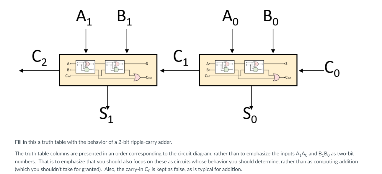
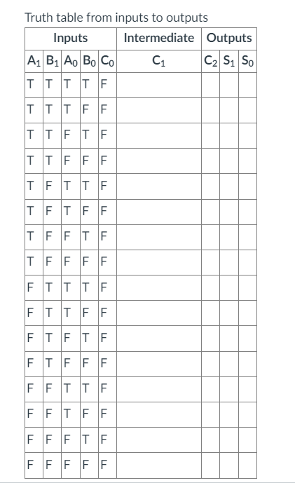
Fill in this a truth table with the behavior of a 2-bit ripple-carry adder. The truth table columns are presented in an order corresponding to the circuit diagram, rather than to emphasize the inputs A1A0 and B1B0 as two-bit numbers. That is to emphasize that you should also focus on these as circuits whose behavior you should determine, rather than as computing addition (which you shouldn't take for granted). Also, the carry-in C0 is kept as false, as is typical for addition. Truth table from inputs to outputsStep by Step Solution
There are 3 Steps involved in it
Step: 1

Get Instant Access to Expert-Tailored Solutions
See step-by-step solutions with expert insights and AI powered tools for academic success
Step: 2

Step: 3

Ace Your Homework with AI
Get the answers you need in no time with our AI-driven, step-by-step assistance
Get Started


