Answered step by step
Verified Expert Solution
Question
1 Approved Answer
Purpose Combinational logic deals with techniques for combining basic logic gates into circuits that perform some desired function. Examples of useful combinational logic circuits are
Purpose
Combinational logic deals with techniques for combining basic logic gates into circuits that
perform some desired function. Examples of useful combinational logic circuits are adders,
decoders, multiplexers, display drivers and keyboard encoders, just to name few. Such circuits
are said to be combinational because they are built without feedback from output to input. The
output of the circuit depends solely on the inputs to the circuit. Moreover, without the presence
of a feedback loop, combinational circuits are memoryless in the sense that they are unable to
store information.
Prior to implementation, any combinational circuit design must first be defined. As with software
design, proper statement of a problem is an important task. Once correctly stated, the problem
can be represented in suitable ways that eventually allow for conversion into the necessary logic
for implementation. The purpose of this second lab is to give you experience constructing a
simple combinational circuit from a written problem description.
Problem Description
Homer, a traveling salesman temporarily laid off from his regular job at the local nuclear power
plant services four cities: Springfield, Shelbyville, Ogdenville, and North Haverbrook. Homer's
problem is that he often makes poor choices on routes between cities and spends more time away
from home and on the road than he does selling his products. This not only exasperates his
current boss, his adoring wife Marge, but also Moe the hometown barkeep who relies on
Homer's normally frequent patronage to remain in business. With the help of Lisa, his much
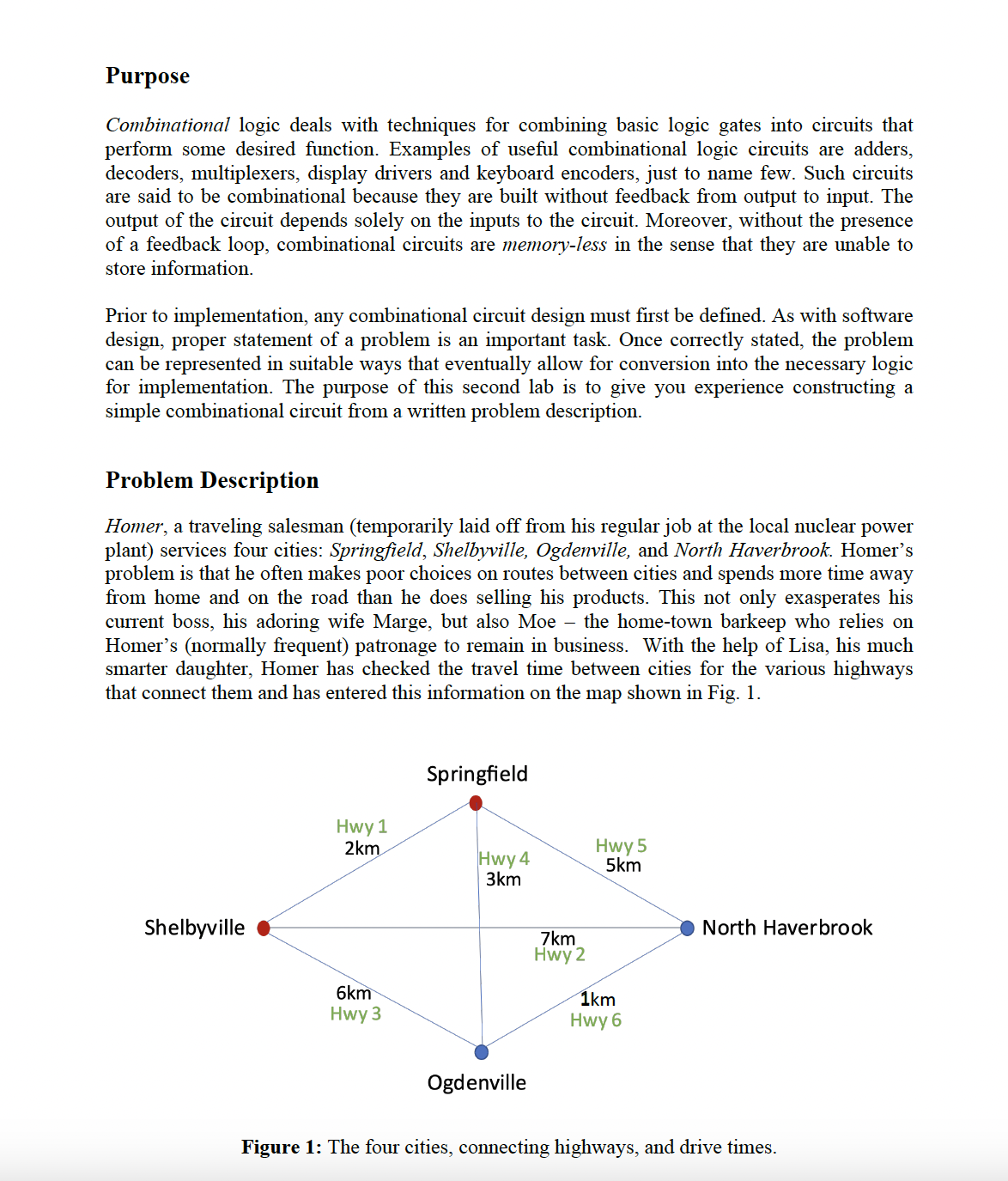
smarter daughter, Homer has checked the travel time between cities for the various highways
that connect them and has entered this information on the map shown in Fig.
Figure : The four cities, connecting highways, and drive times.
Q Following the procedure given in class, identify the inputs and outputs of the combinational logic
device to be designed. You will need to decide how each input and output should be encoded;
that is you will need to decide on the meaning of a logic or logic for each input and each
output. Below, write down the names of each input and output, along with a statement explaining
what it means for an input or output to be at logic versus at logic
Next, draw a blackbox representation of the circuit to be designed using the previous names
for each input and output

Step by Step Solution
There are 3 Steps involved in it
Step: 1

Get Instant Access to Expert-Tailored Solutions
See step-by-step solutions with expert insights and AI powered tools for academic success
Step: 2

Step: 3

Ace Your Homework with AI
Get the answers you need in no time with our AI-driven, step-by-step assistance
Get Started


