Answered step by step
Verified Expert Solution
Question
1 Approved Answer
python Q4. An RL circuit is an electrical circuit consisting of a resistor and an inductor, as shown in the following figure. Voltage V Close
python
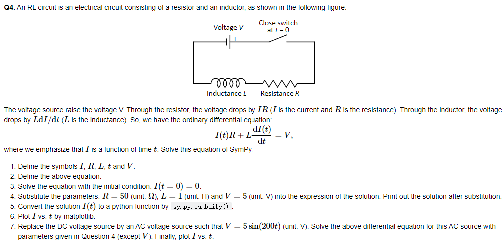
Q4. An RL circuit is an electrical circuit consisting of a resistor and an inductor, as shown in the following figure. Voltage V Close switch at t=0 000 Inductance L Resistance R The voltage source raise the voltage V. Through the resistor, the voltage drops by IR (I is the current and R is the resistance). Through the inductor, the voltage drops by LdI/dt (L is the inductance). So, we have the ordinary differential equation: dl(t) I(t)R+L V, dt where we emphasize that I is function of time t. Solve this equation of Sympy. 1. Define the symbols I, R, L, t and V 2. Define the above equation. 3. Solve the equation with the initial condition: I(t = 0) = 0. 4. Substitute the parameters: R= 50 (unit: S2), L = 1 (unit: H) and V = 5 (unit: V) into the expression of the solution. Print out the solution after substitution. 5. Convert the solution I(t) to a python function by sympy.lambdify(). 6. Plot I vs. t by matplotlib. 7. Replace the DC voltage source by an AC voltage source such that V = 5 sin(200t) (unit: V). Solve the above differential equation for this AC source with parameters given in Question 4 (except V). Finally, plot I vs. tStep by Step Solution
There are 3 Steps involved in it
Step: 1
Get Instant Access to Expert-Tailored Solutions
See step-by-step solutions with expert insights and AI powered tools for academic success
Step: 2
Step: 3
Ace Your Homework with AI
Get the answers you need in no time with our AI-driven, step-by-step assistance
Get Started