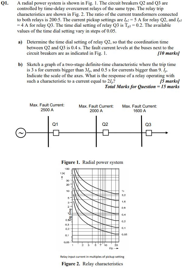
Q1. A radial power system is shown in Fig. 1. The circuit breakers Q2 and Q3 are controlled by time-delay overcurrent relays of the same type. The relay trip characteristics are shown in Fig. 2. The ratio of the current transformers connected to both relays is 200:5. The current pickup settings are 1p2 = 5 A for relay Q2, and 1p3 = 4 A for relay Q3. The time dial setting of relay Q3 is Tp3 = 0.2. The available values of the time dial setting vary in steps of 0.05. a) Determine the time dial setting of relay Q2, so that the coordination time between Q2 and Q3 is 0.4 s. The fault current levels at the buses next to the circuit breakers are as indicated in Fig. 1. [10 marks/ b) Sketch a graph of a two-stage definite-time characteristic where the trip time is 3 s for currents bigger than 31p, and 0.5 s for currents bigger than 9.1. Indicate the scale of the axes. What is the response of a relay operating with such a characteristic to a current equal to 21,? 15 marks) Total Marks for Question = 15 marks Max. Fault Current: 2500 A Max. Fault Current: 2000 A Max. Fault Current: 1600 A Q1 Q2 Q3 Figure 1. Radial power system 100 30 20 10 Tp 3.2 1.6 0,8 time 0.4 02 0.3 0,2 0.1 0.1 0.05 0,05 2 5 710 20 I/Ip Relay input current in multiples of pickup setting Figure 2. Relay characteristics Q1. A radial power system is shown in Fig. 1. The circuit breakers Q2 and Q3 are controlled by time-delay overcurrent relays of the same type. The relay trip characteristics are shown in Fig. 2. The ratio of the current transformers connected to both relays is 200:5. The current pickup settings are 1p2 = 5 A for relay Q2, and 1p3 = 4 A for relay Q3. The time dial setting of relay Q3 is Tp3 = 0.2. The available values of the time dial setting vary in steps of 0.05. a) Determine the time dial setting of relay Q2, so that the coordination time between Q2 and Q3 is 0.4 s. The fault current levels at the buses next to the circuit breakers are as indicated in Fig. 1. [10 marks/ b) Sketch a graph of a two-stage definite-time characteristic where the trip time is 3 s for currents bigger than 31p, and 0.5 s for currents bigger than 9.1. Indicate the scale of the axes. What is the response of a relay operating with such a characteristic to a current equal to 21,? 15 marks) Total Marks for Question = 15 marks Max. Fault Current: 2500 A Max. Fault Current: 2000 A Max. Fault Current: 1600 A Q1 Q2 Q3 Figure 1. Radial power system 100 30 20 10 Tp 3.2 1.6 0,8 time 0.4 02 0.3 0,2 0.1 0.1 0.05 0,05 2 5 710 20 I/Ip Relay input current in multiples of pickup setting Figure 2. Relay characteristics