Answered step by step
Verified Expert Solution
Question
1 Approved Answer
Question 1. (100 POINTS) Use the following Boolean equation for this question: Y AB +ABC+(A C) (Equation 1) 1.?.) (20 POINTS) Write an verilog program
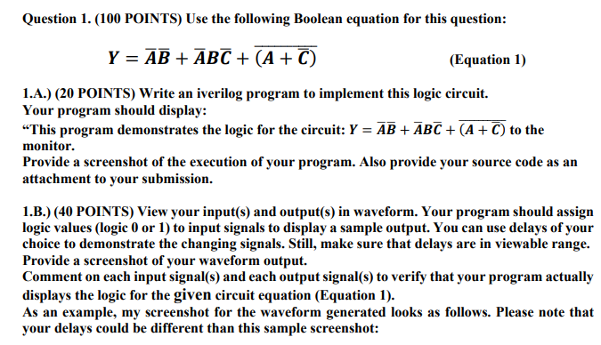
Question 1. (100 POINTS) Use the following Boolean equation for this question: Y AB +ABC+(A C) (Equation 1) 1.?.) (20 POINTS) Write an verilog program to implement this logic circuit. Your program should display: "This program demonstrates the logic for the circuit: Y-AB + ABC + (A + C) to the monitor. Provide a screenshot of the execution of your program. Also provide your source code as an attachment to your submission. 1.B.) (40 POINTS) View your input(s) and output(s) in waveform. Your program should assign logic values (logic 0 or 1) to input signals to display a sample output. You can use delays of your choice to demonstrate the changing signals. Still, make sure that delays are in viewable range. Provide a screenshot of your waveform output. Comment on each input signal(s) and each output signal(s) to verify that your program actually displays the logic for the given circuit equation (Equation 1). As an example, my screenshot for the waveform generated looks as follows. Please note that your delays could be different than this sample screenshot: Question 1. (100 POINTS) Use the following Boolean equation for this question: Y AB +ABC+(A C) (Equation 1) 1.?.) (20 POINTS) Write an verilog program to implement this logic circuit. Your program should display: "This program demonstrates the logic for the circuit: Y-AB + ABC + (A + C) to the monitor. Provide a screenshot of the execution of your program. Also provide your source code as an attachment to your submission. 1.B.) (40 POINTS) View your input(s) and output(s) in waveform. Your program should assign logic values (logic 0 or 1) to input signals to display a sample output. You can use delays of your choice to demonstrate the changing signals. Still, make sure that delays are in viewable range. Provide a screenshot of your waveform output. Comment on each input signal(s) and each output signal(s) to verify that your program actually displays the logic for the given circuit equation (Equation 1). As an example, my screenshot for the waveform generated looks as follows. Please note that your delays could be different than this sample screenshot
Step by Step Solution
There are 3 Steps involved in it
Step: 1
Get Instant Access to Expert-Tailored Solutions
See step-by-step solutions with expert insights and AI powered tools for academic success
Step: 2
Step: 3
Ace Your Homework with AI
Get the answers you need in no time with our AI-driven, step-by-step assistance
Get Started