Answered step by step
Verified Expert Solution
Question
1 Approved Answer
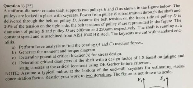
Question 1) [25] A uniform diameter countershaft supports two pulleys B and D as shown in the figure below. The pulleys are locked in

Question 1) [25] A uniform diameter countershaft supports two pulleys B and D as shown in the figure below. The pulleys are locked in place with keyseats. Power from pulley B is transmitted through the shaft and delivered through the belt on pulley D. Assume the belt tension on the loose side of pulley D is 20% of the tension on the tight side. the belt tensions of pulley B are represented in the figure. The diameters of pulley B and pulley D are 500mm and 250mm respectively. The shaft is running at a constant speed and is machined from AISI 1040 HR steel. The keyseats are cut with standard end- mills. a) Perform force analysis to find the bearing (A and C) reaction forces. b) Generate the moment and torque diagram. c) Determine potential critical location(s) for stress design. d) Determine critical diameters of the shaft with a design factor of 1.8 based on fatigue and static stresses at the critical locations using DE-Gerber failure criterion. NOTE: Assume a typical radius at the bottom of the end-mill keyseats for estimating stress- concentration factor. Restrict your work to two iterations. The figure is not drawn to scale. Ft
Step by Step Solution
There are 3 Steps involved in it
Step: 1

Get Instant Access to Expert-Tailored Solutions
See step-by-step solutions with expert insights and AI powered tools for academic success
Step: 2

Step: 3

Ace Your Homework with AI
Get the answers you need in no time with our AI-driven, step-by-step assistance
Get Started


