Question: QUESTION 1. [25 POINTSI In MIPS-16 bits, the R-type format is given as follow: OP (3-bits) Rs(3-bits) Ri{ 3-bits) Rd3-bits) Funct(4-bits) A. Design a code


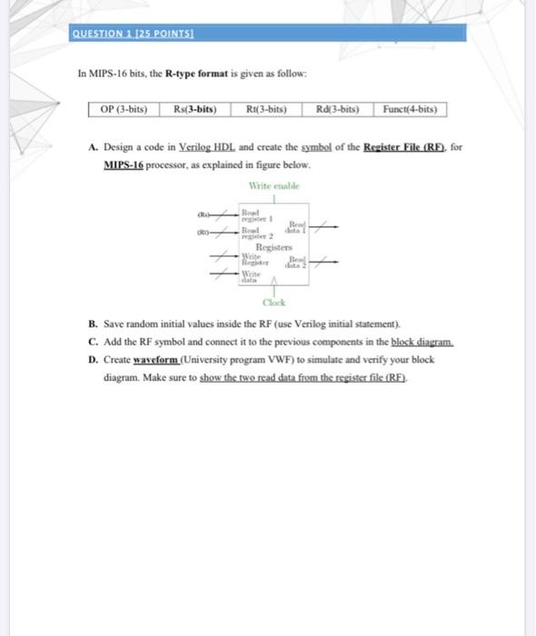
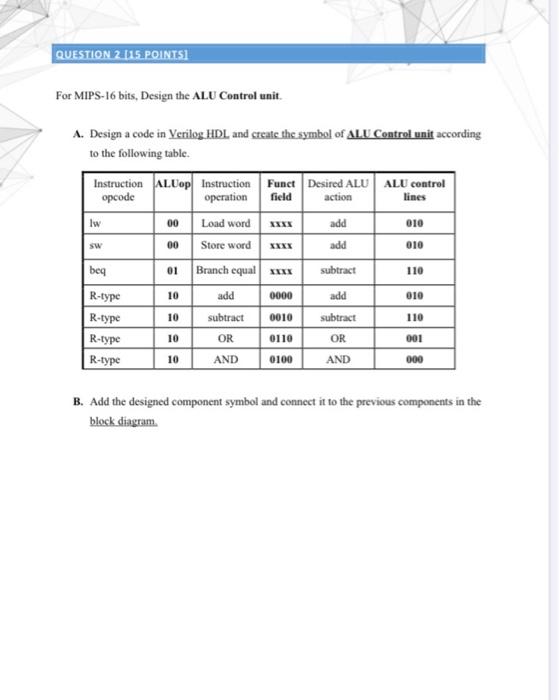
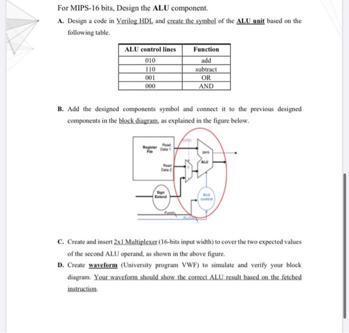
QUESTION 1. [25 POINTSI In MIPS-16 bits, the R-type format is given as follow: OP (3-bits) Rs(3-bits) Ri{ 3-bits) Rd3-bits) Funct(4-bits) A. Design a code in Verilog HDL and create the symbol of the Register File (RF), for MIPS-16 processor, as explained in figure below. Write etable ! Rew R Register Write Write Clock B. Save random initial values inside the RF (use Vetilog initial statement). C. Add the RF symbol and connect it to the previous components in the block diagram D. Create waveform (University program VWF) to simulate and verify your block diagram. Make sure to show the two read data from the register file (RF). QUESTION 2 (15. POINTSI For MIPS-16 bits, Design the ALU Control unit. A. Design a code in Verilog HDL and create the symbol of ALU Control unit according to the following table. Instruction ALUop Instruction Funct Desired ALU ALU control opcode operation lines Load word Store word field action Iw 00 add 010 00 add 010 beq 01 Branch equal xxx subtract 110 10 add 0000 add 010 10 0010 subtract 110 R-type R-type R-type R-type 10 subtract OR AND 0110 OR 001 10 0100 AND 000 B. Add the designed component symbol and connect it to the previous components in the block diagram. For MIPS-16 bits, Design the ALU component. A. Design a code in Verilog HDL and create the symbol of the ALU unit based on the following table. ALU control lines 010 110 001 000 Function add subtract OR AND B. Add the designed components symbol and connect it to the previous designed components in the block diagram, as explained in the figure below. ALU C. Create and insert 2x1 Multiplexer (16-bits input width) to cover the two expected values of the second ALU operand, as shown in the above figure. D. Create waveform (University program VWF) to simulate and verify your block diagram. Your waveform should show the correct ALU result based on the fetched instruction
Step by Step Solution
There are 3 Steps involved in it

Get step-by-step solutions from verified subject matter experts


