Answered step by step
Verified Expert Solution
Question
1 Approved Answer
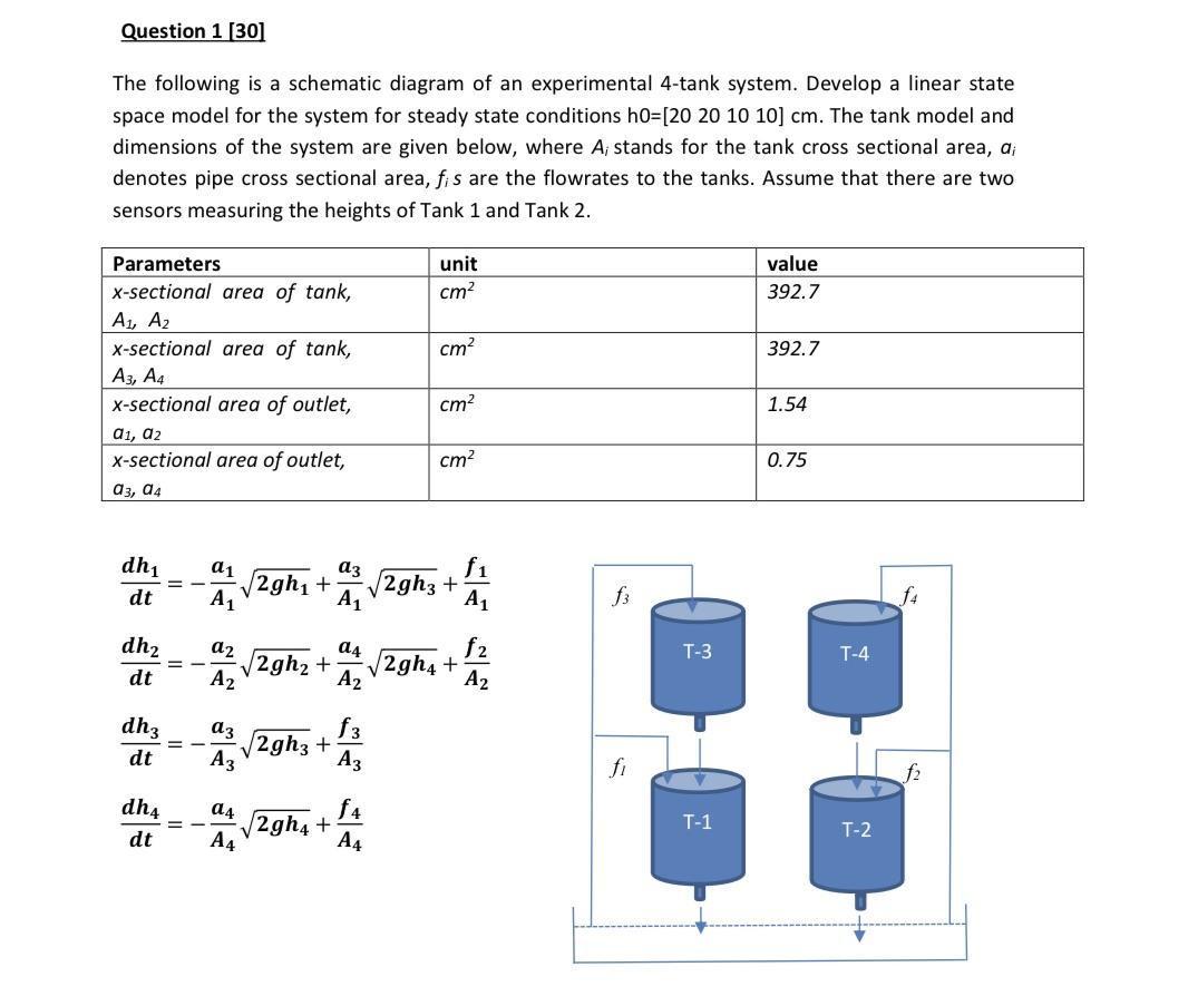
Question 1 [30] The following is a schematic diagram of an experimental 4-tank system. Develop a linear state space model for the system for

Question 1 [30] The following is a schematic diagram of an experimental 4-tank system. Develop a linear state space model for the system for steady state conditions h0=[20 20 10 10] cm. The tank model and dimensions of the system are given below, where A, stands for the tank cross sectional area, di denotes pipe cross sectional area, fis are the flowrates to the tanks. Assume that there are two sensors measuring the heights of Tank 1 and Tank 2. Parameters unit x-sectional area of tank, cm value 392.7 A1, A2 x-sectional area of tank, cm 392.7 A3, A4 x-sectional area of outlet, cm 1.54 a1, a2 x-sectional area of outlet, cm 0.75 03, 04 dh1 = a1 f1 2gh+ 2gh3 + dt A1 A1 A1 3 dh a2 a4 f2 T-3 T-4 = 2gh+ 2gh4+ dt A2 A2 A2 dh3 f3 == 2gh3+ dt A3 A3 dh4 a4 f4 2gh4+ fi T-1 T-2 dt A4 A4 f4 f2
Step by Step Solution
There are 3 Steps involved in it
Step: 1

Get Instant Access to Expert-Tailored Solutions
See step-by-step solutions with expert insights and AI powered tools for academic success
Step: 2

Step: 3

Ace Your Homework with AI
Get the answers you need in no time with our AI-driven, step-by-step assistance
Get Started


