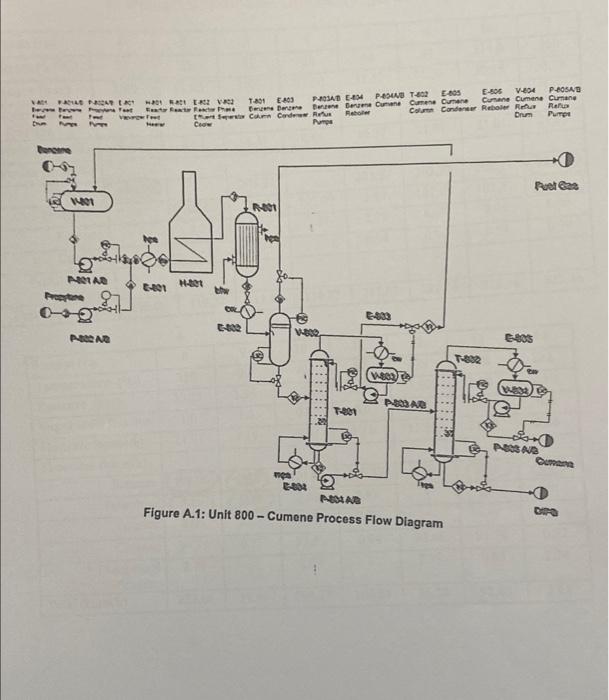
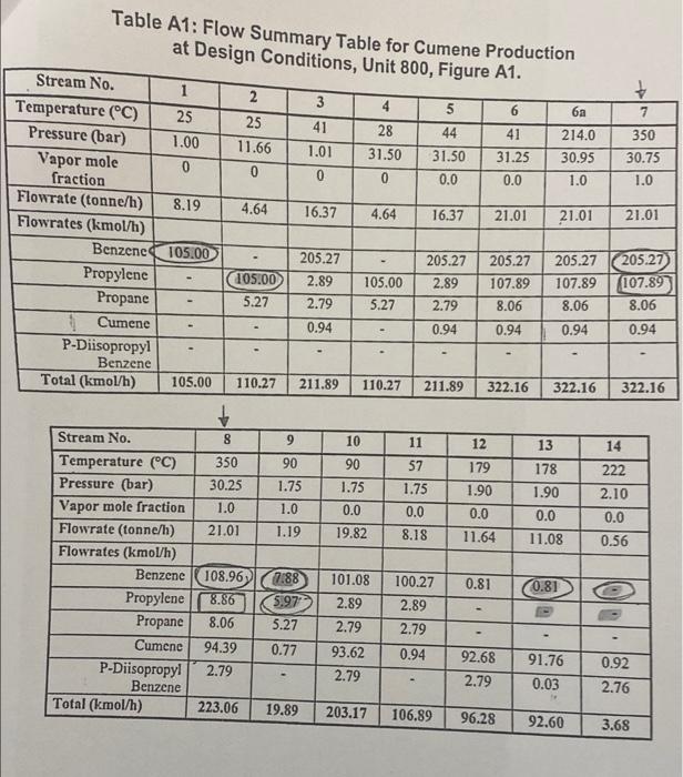
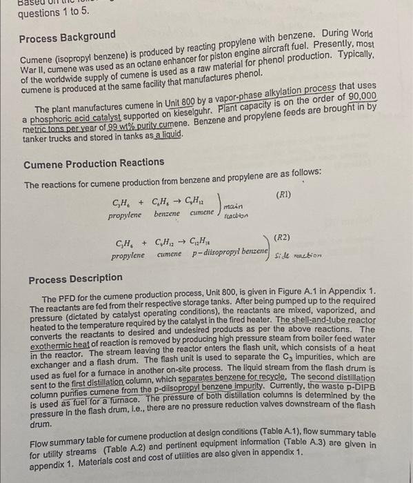
Question 2 [20 marks] Using the conceptual design approaches, develop the input/output structure for the cumene manufacturing process that includes the five steps and yielding the provided process flow diagram (Figure A.1). NA E PAPE we Test 0 EV E-800 PRAD -54 PESU T-802-05 V-804 P-BOSNE 1201 E03 Rahmen Der De Berne Cumane Cumane Curen Cumane Cumene Cumane I Corn Cardewer Reboller Columns Condenser Reboler Rat Rais Drum Pumps Du C Poetas 14401 N001 4,6 NOLAR HT whe Pret 0 VER NOONG B T-BR We PA AB Tee 20 NAR Cum mer 003 NAAR Figure A.1: Unit 800 - Cumene Process Flow Diagram Table A1: Flow Summary Table for Cumene Production at Design Conditions, Unit 800, Figure A1. 2 + 3 5 7 25 11.66 41 1.01 0 350 4 28 31.50 0 6 41 31.25 44 31.50 0.0 214.0 30.95 1.0 30.75 0 0.0 1.0 4.64 16.37 4.64 16.37 21.01 21.01 21.01 Stream No. 1 Temperature (C) 25 Pressure (bar) 1.00 Vapor mole 0 fraction Flowrate (tonne/h) 8.19 Flowrates (kmol/h) Benzene 105.00 Propylene Propane Cumene P-Diisopropyl Benzene Total (kmol/h) 105.00 105.00 5.27 205.27 2.89 2.79 0.94 105.00 5.27 205.27 2.89 2.79 205.27 107.89 8.06 0.94 205.27 205.27 107.89 107.89 8.06 8.06 0.94 0.94 0.94 110.27 211.89 110.27 211.89 322.16 322.16 322.16 8 9 10 11 12 13 14 350 90 90 1.75 1.75 179 1.90 30.25 1.0 21.01 57 1.75 0.0 8.18 1.0 0.0 19.82 178 1.90 0.0 11.08 222 2.10 0.0 0.56 1.19 0.0 11.64 Stream No. Temperature (C) Pressure (bar) Vapor mole fraction Flowrate (tonne/h) Flowrates (kmol/h) Benzene Propylene Propane Cumene P-Diisopropy1 Benzene Total (kmol/h) 0.81 0.81 108.96) 8.86 8.06 94.39 2.79 7.88 5.97 5.27 0.77 101.08 2.89 2.79 93.62 2.79 100.27 2.89 2.79 0.94 92.68 2.79 91.76 0.03 0.92 2.76 223.06 19.89 203.17 106.89 96.28 92.60 3.68 Ba questions 1 to 5. Process Background Cumene (isopropyl benzene) is produced by reacting propylene with benzene. During World War II,cumene was used as an octane enhancer for piston engine aircraft fuel. Presently, most of the worldwide supply of cumene is used as a raw material for phenol production. Typically, cumene is produced at the same facility that manufactures phenol. The plant manufactures cumene in Unit 800 by a vapor-phase alkylation process that uses a phosphoric acid catalyst supported on kieselguhr. Plant capacity is on the order of 90,000 metric tons per year of 99 % purity cumene. Benzene and propylene feeds are brought in by tanker trucks and stored in tanks as a liquid. Cumene Production Reactions The reactions for cumene production from benzene and propylene are as follows: CH + CH, CH2 (RI) maan propylene benzene racion Cumene CH. + CH CH. (R2) propylene cumenep-diisopropyl benzene zene side reaction Process Description The PFD for the cumene production process, Unit 800, is given in Figure A.1 in Appendix 1. The reactants are fed from their respective storage tanks. After being pumped up to the required pressure (dictated by catalyst operating conditions), the reactants are mixed, vaporized, and heated to the temperature required by the catalyst in the fired heater. The shell-and-tube reactor converts the reactants to desired and undesired products as per the above reactions. The exothermic heat of reaction is removed by producing high pressure steam from boiler feed water in the reactor. The stream leaving the reactor enters the flash unit, which consists of a heat exchanger and a flash drum. The flash unit is used to separate the C, impurities, which are used as fuel for a furnace in another on-site process. The liquid stream from the flash drum is sent to the first distillation column, which separates benzene for recycle. The second distillation column purifies cumene from the p-disopropyl benzene impurity. Currently, the waste p-DIPB is used as fuel for a furnace. The pressure of both distillation columns is determined by the pressure in the flash drum, i.e., there are no pressure reduction valves downstream of the flash drum. Flow summary table for cumene production at design conditions (Table A.1), flow summary table for utility streams (Table A.2) and pertinent equipment information (Table A.3) are givent le appendix 1. Materials cost and cost of utilities are also given in appendix 1