Answered step by step
Verified Expert Solution
Question
1 Approved Answer
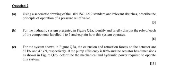
Question 2 (a) Using a schematic drawing of the DIN ISO 1219 standard and relevant sketches, describe the principle of operation of a pressure


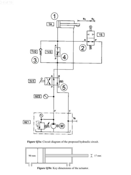
Question 2 (a) Using a schematic drawing of the DIN ISO 1219 standard and relevant sketches, describe the principle of operation of a pressure relief valve. 131 (b) For the hydraulic system presented in Figure Q2a, identify and briefly discuss the role of each of the components labelled 1 to 5 and explain how this system operates. [6] (c) For the system shown in Figure Q2a, the extension and retraction forces on the actuator are 82 kN and 47 kN, respectively. If the pump efficiency is 89% and the actuator has dimensions as shown in Figure Q2b, determine the mechanical and hydraulic power required to operate this system. [11] 34 of 19 021 1A 1) 1V2 3 1V3 (4) 2 1V1 022 AX (5) Figure Q3a: Circuit diagram of the proposed hydraulic circuit. 90 mm Figure Q3b: Key dimensions of the actuator. 15 17 mm
Step by Step Solution
There are 3 Steps involved in it
Step: 1

Get Instant Access to Expert-Tailored Solutions
See step-by-step solutions with expert insights and AI powered tools for academic success
Step: 2

Step: 3

Ace Your Homework with AI
Get the answers you need in no time with our AI-driven, step-by-step assistance
Get Started


