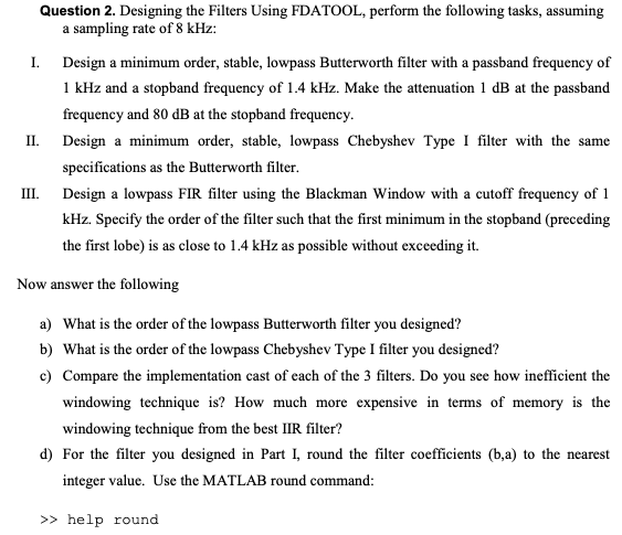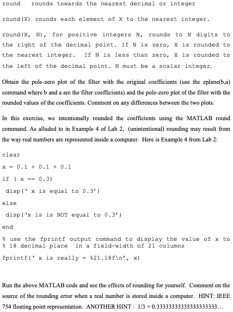

Question 2. Designing the Filters Using FDATOOL, perform the following tasks, assuming a sampling rate of 8 kHz: II. III. I. Design a minimum order, stable, lowpass Butterworth filter with a passband frequency of 1 kHz and a stopband frequency of 1.4 kHz. Make the attenuation 1 dB at the passband frequency and 80 dB at the stopband frequency. Design a minimum order, stable, lowpass Chebyshev Type I filter with the same specifications as the Butterworth filter. Design a lowpass FIR filter using the Blackman Window with a cutoff frequency of 1 kHz. Specify the order of the filter such that the first minimum in the stopband (preceding the first lobe) is as close to 1.4 kHz as possible without exceeding it. Now answer the following a) What is the order of the lowpass Butterworth filter you designed? b) What is the order of the lowpass Chebyshev Type I filter you designed? c) Compare the implementation cast of each of the 3 filters. Do you see how inefficient the windowing technique is? How much more expensive in terms of memory is the windowing technique from the best IIR filter? d) For the filter you designed in Part I, round the filter coefficients (b,a) to the nearest integer value. Use the MATLAB round command: >> help round round rounds towards the nearest decimal or integer round (X) rounds each element of x to the nearest integer. round (X, N), for positive integers N, rounds to N digits to the right of the decimal point. If N is zero, X is rounded to the nearest integer. If N is less than zero, x is rounded to the left of the decimal point. N must be a scalar integer. Obtain the pole-zero plot of the filter with the original coefficients (use the zplane(b,a) command where b and a are the filter coefficients) and the pole-zero plot of the filter with the rounded values of the coefficients. Comment on any differences between the two plots. In this exercise, we intentionally rounded the coefficients using the MATLAB round command. As alluded to in Example 4 of Lab 2, (unintentional) rounding may result from the way real numbers are represented inside a computer. Here is Example 4 from Lab 2: clear x = 0.1 + 0.1 + 0.1 if (x == 0.3) disp('x is equal to 0.3') else disp('x is is NOT equal to 0.3) end f use the fprintf output command to display the value of x to $ 18 decimal place in a field-width of 21 columns fprintf("x is really = $21.18f ', x) Run the above MATLAB code and see the effects of rounding for yourself. Comment on the source of the rounding error when a real number is stored inside a computer. HINT: IEEE 754 floating point representation. ANOTHER HINT: 1/3 = 0.33333333333333333333... Question 2. Designing the Filters Using FDATOOL, perform the following tasks, assuming a sampling rate of 8 kHz: II. III. I. Design a minimum order, stable, lowpass Butterworth filter with a passband frequency of 1 kHz and a stopband frequency of 1.4 kHz. Make the attenuation 1 dB at the passband frequency and 80 dB at the stopband frequency. Design a minimum order, stable, lowpass Chebyshev Type I filter with the same specifications as the Butterworth filter. Design a lowpass FIR filter using the Blackman Window with a cutoff frequency of 1 kHz. Specify the order of the filter such that the first minimum in the stopband (preceding the first lobe) is as close to 1.4 kHz as possible without exceeding it. Now answer the following a) What is the order of the lowpass Butterworth filter you designed? b) What is the order of the lowpass Chebyshev Type I filter you designed? c) Compare the implementation cast of each of the 3 filters. Do you see how inefficient the windowing technique is? How much more expensive in terms of memory is the windowing technique from the best IIR filter? d) For the filter you designed in Part I, round the filter coefficients (b,a) to the nearest integer value. Use the MATLAB round command: >> help round round rounds towards the nearest decimal or integer round (X) rounds each element of x to the nearest integer. round (X, N), for positive integers N, rounds to N digits to the right of the decimal point. If N is zero, X is rounded to the nearest integer. If N is less than zero, x is rounded to the left of the decimal point. N must be a scalar integer. Obtain the pole-zero plot of the filter with the original coefficients (use the zplane(b,a) command where b and a are the filter coefficients) and the pole-zero plot of the filter with the rounded values of the coefficients. Comment on any differences between the two plots. In this exercise, we intentionally rounded the coefficients using the MATLAB round command. As alluded to in Example 4 of Lab 2, (unintentional) rounding may result from the way real numbers are represented inside a computer. Here is Example 4 from Lab 2: clear x = 0.1 + 0.1 + 0.1 if (x == 0.3) disp('x is equal to 0.3') else disp('x is is NOT equal to 0.3) end f use the fprintf output command to display the value of x to $ 18 decimal place in a field-width of 21 columns fprintf("x is really = $21.18f ', x) Run the above MATLAB code and see the effects of rounding for yourself. Comment on the source of the rounding error when a real number is stored inside a computer. HINT: IEEE 754 floating point representation. ANOTHER HINT: 1/3 = 0.33333333333333333333


